Make: Electronics (26 page)
Authors: Charles Platt

Step 1: Slow-Speed Oscillation
Figure 2-103 is a schematic version of the previous PUT breadboard circuit shown in Figure 2-98, drawn so that the layout looks as much like the breadboard as possible.
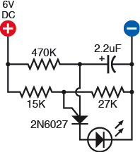
Figure 2-103.
This makes it easier to see what’s happening in the breadboard version.
The 15K resistor and 27K resistor establish the voltage at the gate. The 470K resistor supplies the anode of the PUT, but the PUT begins in its “off” condition, blocking the voltage. So the voltage starts to charge the 2.2 μF capacitor.
You may remember that a resistor slows the rate at which a capacitor accumulates voltage. The bigger the resistor and/or the larger the capacitor, the longer the capacitor takes to reach a full charge. In this circuit, the capacitor takes about five seconds to get close to 6 volts.
Theory
Capacitor Charge Time
The amount of time it takes for a
capacitor to reach its threshold is
calculated with 5RC, where R is the
resistance (in ohms) of the resistor,
and C is the capacitance (in
farads) of the capacitor. So in this
case, you’d multiply 5 by 470,000
by 0.0000022, which gives us 5.17
seconds.
But notice that the PUT is connected directly with the capacitor. Therefore, whatever voltage accumulates on the capacitor is also experienced by the PUT. As the voltage gradually increases, finally it reaches the threshold, which flips the PUT into its “on” state. The capacitor immediately discharges itself through the PUT, through the LED (which flashes), and from there to the negative side of the power supply.
The surge depletes the capacitor. The voltage drops back down, and the PUT returns to its original state. Now the capacitor has to recharge itself all over again, until the whole process repeats itself.
If you substitute a 22 μF capacitor, the charge/discharge cycle should take about 10 times as long, which will give you time to measure it. Set your meter to measure volts DC and place its probes on either side of the capacitor. You can actually watch the charge increasing until it reaches the threshold, at which point the capacitor discharges and the voltage drops back down again.
So now we have an oscillator. What’s next?
Step 2: Beyond the Persistence of Vision
If you substitute a much smaller capacitor, it will charge much more quickly, and the LED will flash faster. Suppose you use a capacitor of 0.0047 μF (which can also be expressed as 47 nanofarads, or 4.7 nF). This seems like an odd number, but it’s a standard value for a capacitor. This will reduce the capacitance by a factor of more than 500, and therefore the LED should flash about 500 times as fast, which should be about 1,000 times per second. The human eye cannot detect such rapid pulses. The human ear, however, can hear frequencies up to 10,000 per second and beyond. If we substitute a miniature loudspeaker for the LED, we should be able to hear the oscillations.
Figure 2-104 shows how I’d like you to make this happen. Please leave your original, slow-flashing circuit untouched, and make a duplicate of it farther down the breadboard, changing a couple of component values as indicated. In the schematic in Figure 2-105, the new part of the circuit is in solid black, while the previous section is in gray.
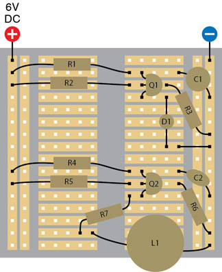
Figure 2-104.
The extra components which have been added at the lower half of the breadboard have the same functions as the components at the top, but some values are slightly different:
R4: 470K
R5: 33K
R6: 27K
R7: 100Ω
C2: 0.0047 μF
Q2: 2N6027
L1: 8Ω 1-inch loudspeaker
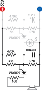
Figure 2-105.
The previous section that you built is shown in gray. Just add the new section in black.
I want you to keep the slow-flashing circuit separately, untouched, because I have an idea to make use of it a little later. You can leave the LED blinking.
The loudspeaker should be wired in series with a 100Ω resistor to limit the current that flows out of the PUT. The loudspeaker doesn’t have any polarity, even though it is fitted with a red wire and a black wire. You can connect it either way around.
Initially, you may be disappointed, because the circuit will not seem to be doing anything. However, if you place your ear very, very close to the loudspeaker, and if you wired the circuit correctly, you should hear a faint buzz, like a mosquito. Obviously, this isn’t loud enough to serve any practical purpose. We need to make it louder. In other words, we need to amplify it.
Maybe you remember that the 2N2222, which you played with previously, can function as an amplifier. So let’s try using that.
Step 3: Amplification
Disconnect the loudspeaker and its 100Ω series resistor. Then add the 2N2222, which is linked with the output from the PUT via a 1K resistor to protect it from excessive current. See Figure 2-107.
The emitter of the 2N2222 is connected to ground, and the collector is supplied through the loudspeaker and its 100Ω series resistor. This way, small fluctuations in the output from the PUT are sensed by the base of the 2N2222 which converts them into bigger fluctuations between the collector and the emitter, which draw current through the loudspeaker. Check the schematic in Figure 2-108.
Now the sound should be louder than an insect buzz, but still not really loud enough to be useful. What to do?
Well—how about if we add another 2N2222? Bipolar transistors can be placed in series, so that the output from the first one goes to the base of the second one. The 240:1 amplification of the first one is multiplied by another 240:1, giving a total amplification of more than 50,000:1.
There are limits to this technique. The 2N2222 can only conduct so much current before getting overloaded, and excess amplification can cause distortion. But when I built this circuit, I used a meter to verify that we’re still within the design limits of a 2N2222, and for this project, I don’t care whether the sound is slightly distorted.
Background
Mounting a loudspeaker
The diaphragm or cone of a loudspeaker is designed to radiate sound, but as it oscillates to and fro, it emits sound from its back side as well as its front side. Because the sounds are opposite in phase, they tend to cancel each other out.
The perceived output from a loudspeaker can increase dramatically if you add a horn around it in the form of a tube to separate the output from the front and back of the speaker. For a miniature 1-inch loudspeaker, you can bend and tape a file card around it. See Figure 2-106.
Better still, mount it in a box so that the box absorbs the sound from the rear of the loudspeaker. For purposes of these simple experiments, I won’t bother to go into the details of vented enclosures and bass-reflex designs.
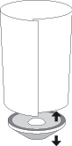
Figure 2-106.
A loudspeaker emits sound from its bottom surface as well as its top surface. To increase the perceived audio volume, use a cardboard tube to separate the two sound sources, or mount the speaker in a small box.
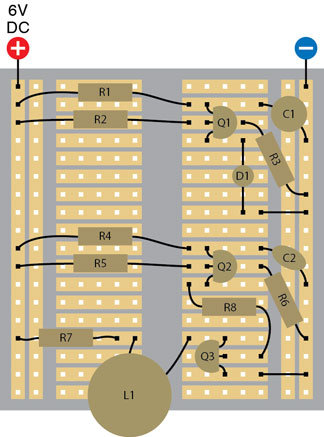
Figure 2-107.
By adding a 2N2222 general-purpose transistor, we amplify the signal
from Q2:
R8: 1K
Q3: 2N2222
Other components are the same as in the previous step in constructing this circuit.
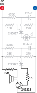
Figure 2-108
.
Add the second 2N2222 as shown in Figure 2-109. In Figure 2-110, once again the previously wired section is in gray.
If the accumulation of electrical components is beginning to seem confusing, remember that each cluster of parts has a separate defined function. We can draw a block diagram to illustrate this, as in Figure 2-112.
Using the second 2N2222, you should find that the output is more clearly audible, at least within the limits of your tiny 1-inch loudspeaker. Cup your hands around it to direct the sound, and you’ll find that the volume seems to increase. You can also try using a 3-inch loudspeaker, which will create a generally better audio output while still remaining within the limits of the little 2N2222 transistor. See Figure 2-106, shown previously, and Figure 2-111.