Structure and Interpretation of Computer Programs (91 page)
Read Structure and Interpretation of Computer Programs Online
Authors: Harold Abelson and Gerald Jay Sussman with Julie Sussman

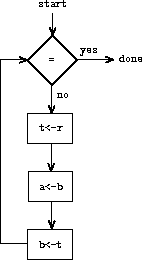
In order for the data paths to actually compute GCDs, the buttons must
be pushed in the correct sequence. We will describe this sequence in
terms of a controller diagram, as illustrated in
figure
5.2
. The elements of the controller
diagram indicate how the
data-path components should be operated. The rectangular boxes in the
controller diagram identify data-path buttons to be pushed, and the
arrows describe the sequencing from one step to the next. The diamond
in the diagram represents a decision. One of the two sequencing
arrows will be followed, depending on the value of the data-path test
identified in the diamond. We can interpret the controller in terms
of a physical analogy: Think of the diagram as a maze in which a
marble is rolling. When the marble rolls into a box, it pushes the
data-path button that is named by the box. When the marble rolls into
a decision node (such as the test for
b
= 0), it leaves the
node on the path determined by the result of the indicated test.
Taken together, the data paths and the controller completely describe
a machine for computing GCDs. We start the controller (the rolling
marble) at the place marked
start
, after placing numbers in
registers
a
and
b
. When the controller reaches
done
, we will find the value of the GCD in register
a
.
 |
Exercise 5.1.
Design a register machine to compute factorials using the iterative
algorithm specified by the following procedure. Draw data-path and
controller diagrams for this machine.
(define (factorial n)
(define (iter product counter)
(if (> counter n)
product
(iter (* counter product)
(+ counter 1))))
(iter 1 1))
Data-path and controller diagrams are adequate for representing simple
machines such as GCD, but they are unwieldy for describing large
machines such as a Lisp interpreter. To make it possible to deal with
complex machines, we will create a language that presents, in textual
form, all the information given by the data-path and controller
diagrams. We will start with a notation that directly mirrors the diagrams.
We define the data paths of a machine by describing the registers and
the operations. To describe a register, we give it a name
and specify the buttons that control assignment to it. We give each
of these buttons a name and specify the source of the data that enters
the register under the button's control. (The source is a register, a
constant, or an operation.)
To describe an operation, we give
it a name and specify its inputs (registers or constants).
We define the controller of a machine as a sequence of
instructions
together with
labels
that identify
entry
points
in the sequence. An instruction is one of the following:
- The name of a data-path button to push to assign a value to
a register. (This corresponds to a box in the controller diagram.) - A
test
instruction, that performs a specified test. - A conditional branch (
branch
instruction) to a
location indicated by a controller label, based on the result of the
previous test. (The test and branch together correspond to a diamond
in the controller diagram.) If the test is false, the controller
should continue with the next instruction in the sequence. Otherwise,
the controller should continue with the instruction after the label. - An unconditional branch (
goto
instruction) naming a
controller label at which to continue execution.
The machine starts at the beginning of the controller instruction
sequence and stops when execution reaches the end of the sequence.
Except when a branch changes the flow of control, instructions are
executed in the order in which they are listed.
(data-paths |
Figure
5.3
shows the GCD machine described in
this way. This example only hints at the generality of these
descriptions, since the GCD machine is a very simple case: Each
register has only one button, and each button and test is used only
once in the controller.
Unfortunately, it is difficult to read such a description. In order
to understand the controller instructions we must constantly refer
back to the definitions of the button names and the operation names,
and to understand what the buttons do we may have to refer to the
definitions of the operation names. We will thus transform our
notation to combine the information from the data-path and controller
descriptions so that we see it all together.
To obtain this form of description, we will replace the arbitrary
button and operation names by the definitions of their behavior. That
is, instead of saying (in the controller) “Push button
t<-r
”
and separately saying (in the data paths) “Button
t<-r
assigns
the value of the
rem
operation to register
t
” and “The
rem
operation's inputs are the contents of registers
a
and
b
,” we will say (in the controller) “Push the
button that assigns to register
t
the value of the
rem
operation on the contents of registers
a
and
b
.”
Similarly, instead of saying (in the controller) “Perform the
=
test” and separately saying (in the data paths) “The
=
test operates on the contents of register
b
and the
constant 0,” we will say “Perform the
=
test on the
contents of register
b
and the constant 0.” We will omit the
data-path description, leaving only the controller sequence. Thus,
the GCD machine is described as follows:
(controller
test-b
(test (op =) (reg b) (const 0))
(branch (label gcd-done))
(assign t (op rem) (reg a) (reg b))
(assign a (reg b))
(assign b (reg t))
(goto (label test-b))
gcd-done)
This form of description is easier to read than the kind illustrated
in figure
5.3
, but it also has disadvantages:
- It is more verbose for large machines,
because complete descriptions of the data-path elements are repeated
whenever the elements are mentioned in the controller instruction
sequence. (This is not a problem in the GCD example, because each
operation and button is used only once.) Moreover, repeating the
data-path descriptions obscures the actual data-path structure of the
machine; it is not obvious for a large machine how many registers,
operations, and buttons there are and how they are interconnected. - Because the controller instructions in a machine definition
look like Lisp expressions, it is easy to forget that they are
not arbitrary Lisp expressions. They can notate only legal machine
operations. For example, operations can operate directly only on
constants and the contents of registers, not on the results of other
operations.
In spite of these disadvantages, we will use this register-machine
language throughout this chapter, because we will be more concerned with
understanding controllers than with understanding the elements and
connections in data paths. We should keep in mind,
however, that data-path design is crucial in designing real machines.
Exercise 5.2.
Use the register-machine language to describe
the iterative factorial machine of exercise
5.1
.
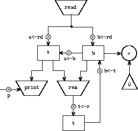
Let us modify the GCD machine so that we can type in the numbers
whose GCD we want and get the answer printed at our terminal. We will
not discuss how to make a machine that can read and print, but will
assume (as we do when we use
read
and
display
in Scheme) that
they are available as primitive operations.
1
Read
is like the operations we have been using in that it
produces a value that can be stored in a register. But
read
does not take inputs from any registers; its value depends on
something that happens outside the parts of the machine we are
designing. We will allow our machine's operations to have such
behavior, and thus will draw and notate the use of
read
just as
we do any other operation that computes a value.
Print
, on the other hand, differs from the operations we have
been using in a fundamental way: It does not produce an output value
to be stored in a register. Though it has an effect, this effect is
not on a part of the machine we are designing. We will refer to this
kind of operation as an
action
. We will represent an action in
a data-path diagram just as we represent an operation that computes a
value – as a trapezoid that contains the name of the action.
Arrows point to the action box from any inputs (registers or
constants). We also associate a button with the action. Pushing the
button makes the action happen. To make a controller push an action
button we use a new kind of instruction called
perform
. Thus,
the action of printing the contents of register
a
is represented
in a controller sequence by the instruction
(perform (op print) (reg a))
Figure
5.4
shows the data paths and controller for
the new GCD machine. Instead of having the machine stop after
printing the answer, we have made it start over, so that it repeatedly
reads a pair of numbers, computes their GCD, and prints the result.
This structure is like the driver loops we used in the interpreters of
chapter 4.
 (controller |
We will often define a machine to include “primitive” operations that are
actually very complex. For example, in sections
5.4
and
5.5
we will treat Scheme's environment
manipulations as primitive. Such abstraction is valuable because it
allows us to ignore the details of parts of a machine so that we can
concentrate on other aspects of the design. The fact that we have
swept a lot of complexity under the rug, however, does not mean that a
machine design is unrealistic. We can always replace the complex
“primitives” by simpler primitive operations.