Make: Electronics (16 page)
Authors: Charles Platt

Fundamentals
All about switches (continued)
Sparking
When you make and break an electrical connection, it tends to create a spark. Sparking is bad for switch contacts. It eats them until the switch doesn’t make a reliable connection anymore. For this reason, you must use a switch that is appropriate for the voltage and amperage that you are dealing with. Electronic circuits generally are low-current, and low-voltage, so you can use almost any switch, but if you are switching a motor, it will tend to suck an initial surge of current that is at least double the rating of the motor when it is running constantly. You should probably use a 4-amp switch to turn a 2-amp motor on and off.
Checking a switch
You can use your meter to check a switch. Doing this helps you find out which contacts are connected when you turn a switch one way or the other. It’s also useful if you have a pushbutton and you can’t remember whether it’s the type that is normally open (you press it to make a connection) or normally closed (you press it to break the connection). Set your meter to measure ohms, and touch the probes to the switch terminals while you work the switch.
This is a hassle, though, because you have to wait while the meter makes an accurate measurement. When you just want to know whether there is a connection, your meter has a “continuity tester” setting. It beeps if it finds a connection, and stays silent if it doesn’t. See Figures 2-30 through 2-32 for examples of meters set to test continuity. Figure 2-33 offers an example of a toggle switch being tested for continuity.
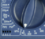
Figure 2-30
.
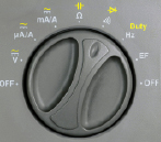
Figure 2-31
.
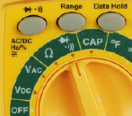
Figure 2-32.
To check a circuit for continuity, turn the dial of your meter to the symbol shown. Only use this feature when there is no power in the component or the circuit that you are testing.
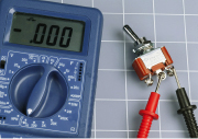
Figure 2-33.
When the switch connects two of its terminals, the meter shows zero resistance between them and will beep if you have set it to verify continuity.
Use the continuity-testing feature on your meter only on circuits or components that have no power in them at the time.
Background
Early switching systems
Switches seem to be such a fundamental feature of our world, and their concept is so simple that it’s easy to forget that they went through a gradual process of development and refinement. Primitive knife switches were quite adequate for pioneers of electricity who simply wanted to connect and disconnect electricity to some apparatus in a laboratory, but a more sophisticated approach was needed when telephone systems began to proliferate. Typically, an operator at a “switchboard” needed a way to connect any pair of 10,000 lines on the board. How could it be done?
In 1878, Charles E. Scribner (Figure 2-34) developed the “jack-knife switch,” so called because the part of it that the operator held looked like the handle of a jackknife. Protruding from it was a plug, and when the plug was pushed into a socket, it made contact inside the socket. The socket, in fact, was the switch.
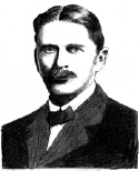
Figure 2-34.
Charles E. Scribner invented the “jack-knife switch” to satisfy the switching needs of telephone systems in the late 1800s. Today’s audio jacks still work on the same basis.
[1]
Audio connectors on guitars and amplifiers still work on the same principle, and when we speak of them as being “jacks,” the term dates back to Scribner’s invention. Switch contacts still exist inside a jack socket.
Today, of course, telephone switchboards have become as rare as telephone operators. First they were replaced with relays—electrically operated switches, which I’ll talk about later in this chapter. And then the relays were superceded by transistors, which made everything happen without any moving parts. Before the end of this chapter, you’ll be switching current using transistors.
[
1
]
The photo on which this drawing is based first appeared in
The History of the Telephone
by Herbert Newton Casson in 1910 (Chicago: A. C. McClurg & Co.).
Introducing Schematics
In Figure 2-35, I’ve redrawn the circuit from
Experiment 6
in a simplified style known as a “schematic.” From this point onward, I will be illustrating circuits with schematics, because they make circuits easier to understand. You just need to know a few symbols to interpret them.
Compare the schematic here with the drawing of the circuit in Figure 2-17. They both show exactly the same thing: Components, and connections between them. The gray rectangles are the switches, the zigzag thing is the resistor, and the symbol with two diagonal arrows is the LED.
The schematic LED symbol includes two arrows indicating that it emits light, because there are some kinds of diodes, which we’ll get to later, that don’t. The triangle inside the diode symbol always points from positive to negative.
Trace the path that electricity can take through the circuit and imagine the switches turning one way or the other. You should see clearly now why either switch will reverse the state of the LED from on to off or off to on.
This same circuit is used in houses where you have a switch at the bottom of a flight of stairs, and another one at the top, both controlling the same lightbulb. The wires in a house are much longer, and they snake around behind the walls, but because their connections are still the same, they could be represented with the same basic schematic. See Figure 2-36.
A schematic doesn’t tell you exactly where to put the components. It just tells you how to join them together. One problem: Different people use slightly different schematic symbols to mean the same thing. Check the upcoming section, “Fundamentals: Basic schematic symbols,” for the details.
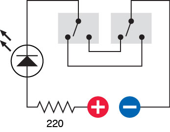
Figure 2-35.
This schematic shows the same circuit as in Figure 2-17 and makes it easier to see how the switches function.
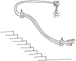
Figure 2-36.
The two-switch circuit shown in Figures 2-17 and 2-35 is often found in house wiring, especially where switches are located at the top and bottom of a flight of stairs. This sketch shows what you might find inside the walls. Wires are joined with “wire nuts” inside boxes that are hidden from everyday view.
Fundamentals
Basic schematic symbols
Schematic symbols are like words in a language: they have mutated over the years into a confusing range of variations. A simple on/off (single-pole, single-throw, or SPST) switch, for instance, can be represented by any of the symbols shown in Figure 2-37. They all mean exactly the same thing.
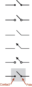
Figure 2-37.
Variations on a theme: Just some of the different styles used to depict a single-pole, single-throw switch in schematic diagrams. The bottom version is the style used in this book.
Figure 2-38 shows double-pole, double-throw switches. A dotted line indicates a mechanical connection inside the switch, so that when you flip it, you affect both the poles simultaneously. Remember, the poles are electrically isolated from each other.
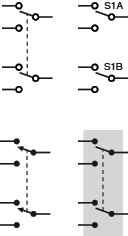
Figure 2-38.
More variations: some different styles for depicting a double-pole, double-throw switch. The style at bottom-right is used in this book.
Once in a while, you may find a schematic in which switches seem to be scattered around, but the way they are identified (such as S1A, S1B, S1C, and so on) tells you that this is really all one switch with multiple poles.
In the schematics in this book, I’ll place a gray rectangle behind each switch. This gray rectangle is not a standard symbol; you won’t find it in other books. I’m just including it to remind you that the parts inside are all contained in one package.
A very important stylistic variation in schematics is the way they show whether wires make a connection with each other. Old schematics used to show a little semicircular bump in a wire if it crossed another wire without making a connection. Because modern circuit-drawing software doesn’t create this style of schematic, it is no longer often used. The modern style, which you are likely to find if you browse through schematics online, can be summarized like this:
- A dot joining two wires indicates an electrical connection.
- No dot indicates no connection.