Make: Electronics (20 page)
Authors: Charles Platt

Figure 2-64.
The oscillator circuit shown in schematic form.
Now, when you press the button, the contacts in their relaxed state feed power to the coil as well as to the lefthand LED. But as soon as the coil is energized, it opens the contacts. This interrupts the power to the coil—so the relay relaxes, and the contacts close again. They feed another pulse of power to the coil, which opens the contacts again, and the cycle repeats endlessly.
Because we’re using a very small relay, it switches on and off extremely fast. In fact, it oscillates perhaps 50 times per second (too fast for the LEDs to show what’s really happening). Make sure your circuit looks like the one in the diagram, and then press the pushbutton very briefly. You should hear the relay make a buzzing sound. If you have impaired hearing, touch the relay lightly with your finger, and you should feel the relay vibrating.
When you force a relay to oscillate like this, it’s liable to burn itself out or destroy its contacts. That’s why I asked you to press the pushbutton briefly. To make the circuit more practical, we need something to slow the relay down and prevent it from self-destructing. That necessary item is a capacitor.
Adding Capacitance
Add a 1,000 μF electrolytic capacitor in parallel with the coil of the relay as shown in the diagram in Figure 2-65 and the schematic in Figure 2-66. Check Figure 2-14 if you’re not sure what a capacitor looks like. The 1,000 μF value will be printed on the side of it, and I’ll explain what this means a little later.
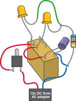
Figure 2-65.
Adding a capacitor makes the relay oscillate more slowly.
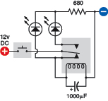
Figure 2-66.
The capacitor appears at the bottom of this schematic diagram.
Make sure the capacitor’s
short
wire is connected to the
negative
side of the circuit; otherwise, it won’t work. In addition to the short wire, you should find a minus sign on the body of the capacitor, which is there to remind you which side is negative. Electrolytic capacitors are fussy about this.
When you press the button now, the relay should click slowly instead of buzzing. What’s happening here?
A capacitor is like a tiny rechargeable battery. It’s so small that it charges in a fraction of a second, before the relay has time to open its lower pair of contacts. Then, when the contacts are open, the capacitor acts like a battery, providing power to the relay. It keeps the coil of the relay energized for about one second. After the capacitor exhausts its power reserve, the relay relaxes and the process repeats.
Fundamentals
Farad basics
The Farad is an international unit to measure capacitance. Modern circuits usually require small capacitors. Consequently it is common to find capacitors measured in microfarads (one-millionth of a farad) and even picofarads (one-trillionth of a farad). Nanofarads are also used, more often in Europe than in the United States. See the following conversion table.
0.001 nanofarad | 1 picofarad | 1 pF |
0.01 nanofarad | 10 picofarads | 10 pF |
0.1 nanofarad | 100 picofarads | 100 pF |
1 nanofarad | 1,000 picofarads | 1,000 pF |
0.001 microfarad | 1 nanofarad | 1 nF |
0.01 microfarad | 10 nanofarads | 10 nF |
0.1 microfarad | 100 nanofarads | 100 nF |
1 microfarad | 1,000 nanofarads | 1,000 nF |
0.000001 Farad | 1 microfarad | 1 mF |
0.00001 Farad | 10 microfarads | 10 mF |
0.0001 Farad | 100 microfarads | 100 mF |
0.001 Farad | 1,000 microfarads | 1,000 mF |
(You may encounter capacitances greater than 1,000 microfarads, but they are uncommon.)
Fundamentals
Capacitor basics
DC current does not flow through a capacitor, but voltage can accumulate very quickly inside it, and remains after the power supply is disconnected. Figures 2-67 and 2-68 may help to give you an idea of what happens inside a capacitor when it is fully charged.
 Getting Zapped by Capacitors
If a large capacitor is charged with a high voltage, it can retain that voltage for a long time. Because the circuits in this book use low voltages, you don’t have to be concerned about that danger here, but if you are reckless enough to open an old TV set and start digging around inside (which I do not recommend), you may have a nasty surprise. An undischarged capacitor can kill you as easily as if you stick your finger into an electrical outlet. Never touch a large capacitor unless you really know what you’re doing.

Figure 2-67.
When DC voltage reaches a capacitor, no current flows, but the capacitor charges itself like a little battery. The positive and negative charges are equal and opposite.
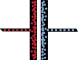
Figure 2-68.
You can imagine positive “charge particles” accumulating on one side of the capacitor and attracting negative “charge particles” to the opposite side.
In most modern electrolytic capacitors, the plates have been reduced to two strips of very thin, flexible, metallic film, often wrapped around each other, separated by an equally thin insulator. Disc ceramic capacitors typically consist of just a single disc of nonconductive material with metal painted on both sides and leads soldered on.
The two most common varieties of capacitors are ceramic (capable of storing a relatively small charge) and electrolytic (which can be much larger). Ceramics are often disc-shaped and yellow in color; electrolytics are often shaped like miniature tin cans and may be just about any color. Refer back to Figures 2-14 and 2-15 for some examples.
Fundamentals
Capacitor basics (continued)
Ceramic capacitors have no polarity, meaning that you can apply negative voltage to either side of them. Electrolytics do have polarity, and won’t work unless you connect them the right way around.
The schematic symbol for a capacitor has two significant variants: with two straight lines (symbolizing the plates inside a capacitor), or with one straight line and one curved line, as shown in Figure 2-69. When you see a curved line, that side of the capacitor should be more negative than the other. The schematic symbol may also include a + sign. Unfortunately, some people don’t bother to draw a curved plate on a polarized capacitor, yet others draw a curved plate even on a nonpolarized capacitor.

Figure 2-69.
The generic schematic for a capacitor is on the left. The version on the right indicates a polarized capacitor which requires its left plate to be “more positive” than its right plate. The plus sign is often omitted.
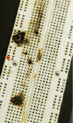
Figure 2-70.
A tantalum capacitor was plugged into this breadboard, accidentally connected the wrong way around to a power source capable of delivering a lot of current. After a minute or so of this abuse, the capacitor rebelled by popping open and scattering small flaming pieces, which burned their way into the plastic of the breadboard. Lesson learned: observe polarity!
 Capacitor Polarity
You must connect an electrolytic capacitor so that its longer wire is more positive than its shorter wire. The shell of the capacitor is usually marked with a negative sign near the shorter wire.
Some capacitors may behave badly if you don’t observe their polarity. One time I connected a tantalum capacitor to a circuit, using a power supply able to deliver a lot of current, and was staring at the circuit and wondering why it wasn’t working when the capacitor burst open and scattered little flaming fragments of itself in a 3-inch radius. I had forgotten that tantalum capacitors can be fussy about positive and negative connections. Figure 2-70 shows the aftermath.