Make: Electronics (57 page)
Authors: Charles Platt

Fundamentals
Rules for connecting logic gates (continued)
Not permitted:
- No floating-input pins! On CMOS chips such as the HC family, you must always connect all input pins with a known voltage, even if they supply a gate on the chip that you’re not using. When you use a SPST switch to control an input, remember that in its “off” position, it leaves the input unconnected. Use a pull-up or pull-down resistor to prevent this situation. See Figure 4-77.
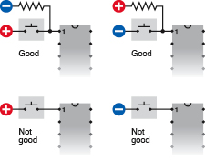
Figure 4-77.
Because a CMOS chip is so sensitive to input fluctuations, a logical input should never be left “floating,” or unattached to a defined voltage source. This means that any single-throw switch or pushbutton should be used with a pull-up or pull-down resistor, so that when the contacts are open, the input is still defined. - Don’t use an unregulated power supply, or more than 5 volts, to power 74HCxx or 74LSxx logic gates.
- Be careful when using the output from a logic gate to power even a low-current LED. Check how many milliamps are being drawn. Also be careful when “sharing” the output from a logic gate with the input of another gate, at the same time that it is driving an LED. The LED may pull down the output voltage, to a point where the other gate won’t recognize it. Always check currents and voltages when modifying a circuit or designing a new one.
- Never apply a significant voltage or current to the output pin of a logic gate. In other words, don’t force an input into an output.
- Never link the outputs from two or more logic gates. If they must share a common output wire, use diodes to protect them from each other. See Figure 4-78.
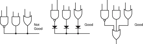
Figure 4-78.
The output from one logic gate must not be allowed to feed back into the output from another logic gate. Diodes can be used to isolate them, or they can be linked via another gate.
In the 74HCxx logic family, each input of a logic gate consumes just a microamp, while the output can source 4 milliamps. This seems paradoxical: how can the chip give out more than it takes in? The answer is that it also consumes power from the power supply attached to pins 7 and 14. That’s where the additional electricity comes from.
Because the logical output from a chip can be greater than the logical input, we can put the chip in a state where it keeps itself “switched on” in a way which is similar to the way the relay in the alarm project was wired to lock itself on. The simplest way to do this in a logic chip is by feeding some of the output back to one of the inputs.
Figure 4-79 shows an AND gate with one of its inputs wired to positive and its other input held low by a pull-down resistor, with a pushbutton that can make the input high. A signal diode connects the output of the chip back to the pushbutton-controlled input. Remember that the diode has a mark on it indicating the end which should be connected to the
negative
side of the power supply, which in this case will be the end of the 10K resistor.
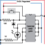
Figure 4-79.
Using a diode, the logical output from a gate can be allowed to feed back to one of its inputs, so that the gate latches after receiving a brief logical input pulse.
The schematic in Figure 4-79 shows how the circuit should look in breadboard format. Figure 4-80 shows it in a simpler format.
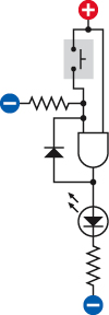
Figure 4-80.
The breadboard-format schematic in is simplified here to show more clearly the way in which a gate can latch itself after receiving an input pulse.
From this point on, I won’t bother to show the power regulator and the capacitors associated with it. Just remember to include them every time you see the power supply labeled as “5V DC Regulated.”
When you switch on the power, the LED is dark, as before. The AND gate needs a positive voltage on both of its logical inputs, to create a positive output, but it now has positive voltage only on one of its inputs, while the other input is pulled down by the 10K resistor. Now touch the pushbutton, and the LED comes on. Let go of the pushbutton, and the LED stays on, because the positive output from the AND gate circulates back through the diode and is high enough to overcome the negative voltage coming through the pull-down resistor.
The output from the AND gate is powering its own input, so the LED will stay on until we disconnect it. This arrangement is a simple kind of “latch,” and can be very useful when we want an output that continues after the user presses and releases a button.
You can’t just connect the output from the gate to one of its inputs using an ordinary piece of wire, because this would allow positive voltage from the tactile switch to flow around and interfere with the output signal. Remember, you must never apply voltage to the output pin of a logic gate. The diode prevents this from happening.
If you’ve grasped the basics of logic gates, you’re ready now to continue to our first real project, which will use all the information that I’ve set out so far.
Experiment 20: A Powerful Combination
Suppose you want to prevent other people from using your computer. I can think of two ways to do this: using software, or using hardware. The software would be some kind of startup program that intercepts the normal boot sequence and requests a password. You could certainly do it that way, but I think it would be more fun (and more relevant to this book) to do it with hardware. What I’m imagining is a numeric keypad requiring the user to enter a secret combination before the computer can be switched on.
 The Warranty Issue
If you follow this project all the way to its conclusion, you’ll open your desktop computer, cut a wire, and saw a hole in the cabinet. Without a doubt, this will void your warranty. If this makes you nervous, here are three options:
1. Breadboard the circuit for fun, and leave it at that.
2. Use the numeric keypad on some other device.
3. Use it on an old computer.
You will need:
- Numeric keypad. As specified in the shopping list at the beginning of this chapter, it must have a “common terminal” or “common output.” The schematic in Figure 4-82 shows what I mean. Inside the keypad, one conductor (which I have colored red to distinguish it from the others) connects with one side of every pushbutton. This conductor is “common” to all of them. It emerges from the keypad on an edge connector or set of pins at the bottom, which I’ve colored yellow.
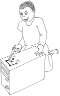
Figure 4-81.
Caution: This just might void your warranty.
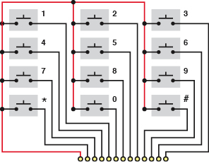
Figure 4-82.
A keypad of the type required for
Experiment 20
incorporates a common terminal connected to one side of each of the 12 pushbuttons. The wire from the common terminal is shown red, here, to make it more easily identifiable.
- Keypads that use “matrix encoding” won’t work with the circuit that I’m going to describe. If the Velleman keypad, which I recommend, is unavailable, and you can’t find another like it, you can use 12 separate SPST pushbuttons. Of course, that will cost a little more.
- 74HC08 logic chip containing four AND gates. Quantity: 1.
- 74HC04 logic chip containing six inverters. Quantity: 1.
- 555 timer chip. Quantity: 1.
- Latching relay, 5 volt, DPST or DPDT, “2 form C” package, Panasonic DS2E-SL2-DC5V or similar. Must have two separate coils (one to latch, one to unlatch) with separate inputs. Quantity: 1.
- LEDs, 5mm generic, your choice of colors. Quantity: 3.
- Ribbon cable, with six conductors minimum, if you want to do a really neat job. You can use a cable of the type sold for hard drives, and split off the six conductors that you need, or shop around on eBay.
- Tools to open your computer, drill four holes, and make saw cuts between the holes, to create a rectangular opening for the keypad (if you want to take this project to its conclusion). Also, four small bolts to attach the keypad to the computer cabinet after you create the opening for it.