Make: Electronics (54 page)
Authors: Charles Platt

Background
From Boole to Shannon (continued)
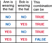
Figure 4-52.
The hat-wearing possibilities can be expressed in a “truth table.”
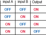
Figure 4-53.
The truth-table from Figure 4-52 can be relabeled to describe the inputs and outputs of a NAND gate.
A very simple telephone problem could be expressed like this. Suppose two customers in a rural area share one telephone line. If one of them wants to use the line, or the other wants to use it, or neither of them wants to use it, there’s no problem. But they cannot both use it at once. You may notice that this is exactly the same as the hat-wearing situation for Ann and Bob.
We can easily draw a circuit using two normally closed relays that creates the desired outcome (see Figure 4-54), but if you imagine a telephone exchange serving many thousands of customers, the situation becomes very complicated indeed. In fact, in Shannon’s time, no logical process existed to find the best solution and verify that it used fewer components than some other solution.
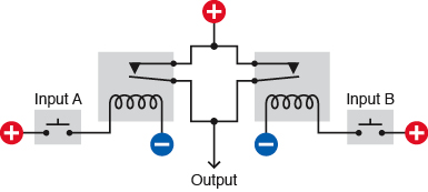
Figure 4-54.
This relay circuit could illustrate the desired logic for two telephone customers wanting to share one line, and its behavior is almost identical to that of the NAND schematic shown in Figure 4-48.
Shannon saw that Boolean analysis could be used for this purpose. Also, if you used an “on” condition to represent numeral 1 and an “off” condition to represent numeral 0, you could build a system of relays that could count. And if it could count, it could do arithmetic.
When vacuum tubes were substituted for relays, the first practical digital computers were built. Transistors took the place of vacuum tubes, and integrated circuit chips replaced transistors, leading to the desktop computers that we now take for granted today. But deep down, at the lowest levels of these incredibly complex devices, they still use the laws of logic discovered by George Boole. Today, when you use a search engine online, if you use the words AND and OR to refine your search, you’re actually using Boolean operators.
Essentials
Logic gate basics
The NAND gate is the most fundamental building block of digital computers, because (for reasons which I don’t have space to explain here) it enables digital addition. If you want to explore more try searching online for topics such as “binary arithmetic” and “half-adder.”
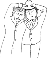
Figure 4-55.
Ann and Bob attempt to overcome the limitations of Boolean logic.
Generally, there are seven types of logic gates:
- AND
- NAND
- OR
- NOR
- XOR
- XNOR
- NOT
Of the six two-input gates, the XNOR is hardly ever used. The NOT gate has a single input, and simply gives a negative output when the input is positive or a positive output when the input is negative. The NOT is more often referred to as an “Inverter.” The symbols for all seven gates are shown in Figure 4-56.
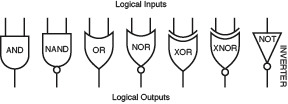
Figure 4-56.
American symbols for the six types of two-input logic gates, and the single-input inverter.
I’ve shown the American symbols. Other symbols have been adopted in Europe, but the traditional symbols shown here are the ones that you will usually find, even being used by Europeans. I also show the truth tables, in Figure 4-57, illustrating the logical output (high or low) for each pair of inputs of each type of gate.
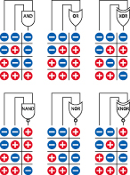
Figure 4-57.
Inputs and corresponding outputs for the six types of logic gates (note that the XNOR gate is seldom used). The minus signs indicate low voltage, close to ground potential. The plus signs indicate higher voltage, close to the positive potential of the power supply in the circuit. The exact voltages will vary depending on other components that may be actively connected.
Essentials
Logic gate basics (continued)
If you have difficulty visualizing logic gates, a mechanical comparison may help. You can think of them as being like sliding plates with holes in them, in a bubblegum machine. Two people, A and B, can push the plates. These people are the two inputs, which are considered positive when they are doing something. (Negative logic systems also exist, but are uncommon, so I’m only going to talk about positive systems here.)
The flow of bubblegum represents a flow of positive current. The full set of possibilities is shown in Figures 4-58 through 4-63.
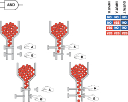
Figure 4-58
.
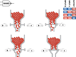
Figure 4-59
.
Essentials
Logic gate basics (continued)
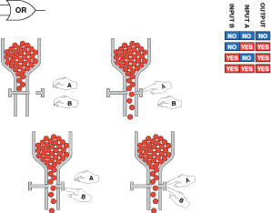
Figure 4-60
.
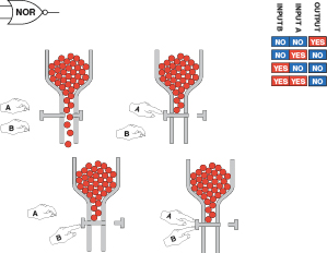
Figure 4-61
.