Make: Electronics (46 page)
Authors: Charles Platt

As long as the
trigger
voltage is
high
, the timer
will not
emit a pulse. (It emits a pulse when the trigger voltage drops.)
As long as the
reset
voltage is
high
, the timer is
able
to emit a pulse. (It shuts down when the reset voltage drops.)
R5 and R6 are known as “pull-up resistors” because they pull the voltage up. You can easily overwhelm them by adding a direct connection to the negative side of the power supply. A typical pull-up resistor for the 555 timer is 10K. With a 9-volt power supply, it only passes 0.9mA (by Ohm’s Law).
Finally, you may be wondering about the purpose of C5, attached to pin 5. This pin is known the “control” pin, which means that if you apply a voltage to it, you can control the sensitivity of the timer. I’ll get to this in more detail a little later. Because we are not using this function right now, it’s good practice to put a capacitor on pin 5 to protect it from voltage fluctuations and prevent it from interfering with normal functioning.
Make sure you become familiar with the basic functioning of the 555 timer before you continue.
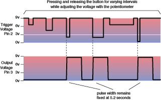
Figure 4-17.
The top graph shows voltage on the trigger (pin 2) when the pushbutton is pressed, for different intervals, at different settings of the potentiometer. The lower graph shows the output (pin 3), which rises until it is almost equal to the power supply, when the voltage on pin 2 drops below 1/3 the full supply voltage.
Fundamentals
The following table shows 555 pulse duration in monostable mode:
- Duration is in seconds, rounded to two figures.
- The horizontal scale shows common resistor values between pin 7 and positive supply voltage.
- The vertical scale shows common capacitor values between pin 6 and negative supply voltage.
To calculate a different pulse duration, multiply resistance × capacitance × 0.0011 where resistance is in kilohms, capacitance is in microfarads, and duration is in seconds.
47 µF | 0.05 | 0.11 | 0.24 | 0.52 | 1.10 | 2.40 | 5.20 | 11.00 | 24.00 | 52.00 |
22 µF | 0.02 | 0.05 | 0.11 | 0.24 | 0.53 | 1.10 | 2.40 | 05.30 | 11.00 | 24.00 |
10 µF | 0.01 | 0.02 | 0.05 | 0.11 | 0.24 | 0.52 | 1.10 | 02.40 | 05.20 | 11.00 |
04.7 µF | 0.01 | 0.02 | 0.05 | 0.11 | 0.24 | 0.52 | 01.10 | 02.40 | 05.20 | |
02.2 µF | 0.01 | 0.02 | 0.05 | 0.11 | 0.24 | 00.53 | 01.10 | 02.40 | ||
01.0 µF | 0.01 | 0.02 | 0.05 | 0.11 | 00.24 | 00.52 | 01.10 | |||
00.47 µF | 0.01 | 0.02 | 0.05 | 00.11 | 00.24 | 00.52 | ||||
00.22 µF | 0.01 | 0.02 | 00.05 | 00.11 | 00.24 | |||||
00.1 µF | 0.01 | 00.02 | 00.05 | 00.11 | ||||||
00.047 µF | 00.01 | 00.02 | 00.05 | |||||||
00.022 µF | 00.01 | 00.02 | ||||||||
00.01 µF | 00.01 | |||||||||
1K | 2K2 | 4K7 | 10K | 22K | 47K | 100K | 220K | 470K | 1M |
Theory
Inside the 555 timer: monostable mode
The plastic body of the 555 timer contains a wafer of silicon on which are etched dozens of transistor junctions in a pattern that is far too complex to be explained here. However, I can summarize their function by dividing them into groups, as shown in Figure 4-18. An external resistor and two external capacitors are also shown, labeled the same way as in Figure 4-15.
The negative and positive symbols inside the chip are power sources which actually come from pins 1 and 8, respectively. I omitted the internal connections to those pins for the sake of clarity.
The two yellow triangles are “comparators.” Each comparator compares two inputs (at the base of the triangle) and delivers an output (from the apex of the triangle) depending on whether the inputs are similar or different. We’ll be using comparators for other purposes later in this book.
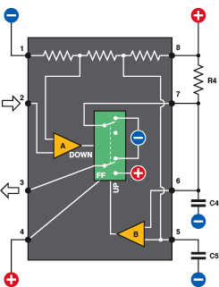
Figure 4-18.
Inside the 555 timer. White lines indicate connections inside the chip. A and B are comparators. FF is a flip-flop which can rest in one state or the other, like a double-throw switch. A drop in voltage on pin 2 is detected by comparator A, which triggers the flip-flop into its “down” position and sends a positive pulse out of pin 3. When C4 charges to 2/3 of supply voltage, this is detected by comparator B, which resets the flip-flop to its “up” position. This discharges C4 through pin 7.
Theory
Inside the 555 timer: monostable mode (continued)
The green rectangle, identified as “FF,” is a “flip-flop.” I have depicted it as a DPDT switch, because that’s how it functions here, although of course it is really solid-state.
Initially when you power up the chip, the flip-flop is in its “up” position which delivers low voltage through the output, pin 3. If the flip-flop receives a signal from comparator A, it flips to its “down” state, and flops there. When it receives a signal from comparator B, it flips back to its “up” state, and flops there. The “UP” and “DOWN” labels on the comparators will remind you what each one does when it is activated.
Flip-flops are a fundamental concept in digital electronics. Computers couldn’t function without them.
Notice the external wire that connects pin 7 with capacitor C4. As long as the flip-flop is “up,” it sinks the positive voltage coming through R4 and prevents the capacitor from charging positively.
If the voltage on pin 2 drops to 1/3 of the supply, comparator A notices this, and flips the flip-flop. This sends a positive pulse out of pin 3, and also disconnects the negative power through pin 7. So now C4 can start charging through R4. While this is happening, the positive output from the timer continues.
As the voltage increases on the capacitor, comparator B monitors it through pin 6, known as the threshold. When the capacitor accumulates 2/3 of the supply voltage, comparator B sends a pulse to the flip-flop, flipping it back into its original state. This discharges the capacitor through pin 7, appropriately known as the discharge pin. Also, the flip-flop ends the positive output through pin 3 and replaces it with a negative voltage. This way, the 555 returns to its original state.
I’ll sum up this sequence of events very simply:
1.
Initially, the flip-flop grounds the capacitor and grounds the output (pin 3).
2.
A drop in voltage on pin 2 to 1/3 the supply voltage or less makes the output (pin 3) positive and allows capacitor C4 to start charging through R4.
3.
When the capacitor reaches 2/3 of supply voltage, the chip discharges the capacitor, and the output at pin 3 goes low again.
In this mode, the 555 timer is “monostable,” meaning that it just gives one pulse, and you have to trigger it again to get another.
You adjust the length of each pulse by changing the values of R4 and C4. How do you know which values to choose? Check the table on
page 157
, which gives an approximate idea and also includes a formula so that you can calculate values of your own.
I didn’t bother to include pulses shorter than 0.01 second in the table, because a single pulse of this length is usually not very useful. Also I rounded the numbers in the table to 2 significant figures, because capacitor values are seldom more accurate than that.
Background
How the timer was born
Back in 1970, when barely a half-dozen corporate seedlings had taken root in the fertile ground of Silicon Valley, a company named Signetics bought an idea from an engineer named Hans Camenzind. It wasn’t a huge breakthrough concept—just 23 transistors and a bunch of resistors that would function as a programmable timer. The timer would be versatile, stable, and simple, but these virtues paled in comparison to its primary selling point. Using the emerging technology of integrated circuits, Signetics could reproduce the whole thing on a silicon chip.

Figure 4-19.
Hans Camenzind, inventor and developer of the 555 timer chip for Signetics.
This entailed some trial and error. Camenzind worked alone, building the whole thing initially on a large scale, using off-the-shelf transistors, resistors, and diodes on a breadboard. It worked, so then he started substituting slightly different values for the various components to see whether the circuit would tolerate variations during production and other factors such as changes in temperature when the chip was in use. He made at least 10 different versions of the circuit. It took months.
Next came the crafts work. Camenzind sat at a drafting table and used a specially mounted X-Acto knife to scribe his circuit into a large sheet of plastic. Signetics then reduced this image photographically by a ratio of about 300:1. They etched it into tiny wafers, and embedded each of them in a half-inch rectangle of black plastic with the product number printed on top. Thus, the 555 timer was born.
It turned out to be the most successful chip in history, both in the number of units sold (tens of billions and counting) and the longevity of its design (unchanged in almost 40 years). The 555 has been used in everything from toys to spacecraft. It can make lights flash, activate alarm systems, put spaces between beeps, and create the beeps themselves.
Today, chips are designed by large teams and tested by simulating their behavior using computer software. Thus, chips inside a computer enable the design of more chips. The heyday of solo designers such as Hans Camenzind is long gone, but his genius lives inside every 555 timer that emerges from a fabrication facility. (If you’d like to know more about chip history, see
http://www.semiconductormuseum.com/Museum_Index.htm
.)