Make: Electronics (43 page)
Authors: Charles Platt

Final Test
When you’ve completed the circuit, test it! If you don’t have your network of magnetic sensor switches set up yet, you can just use a piece of wire to connect the two binding posts. Make sure that S1 is in its Off position, then solder the appropriate plug to your 12-volt power source, and plug it into the power jack. When you press the button, the green LED should light up to show continuity between the two binding posts. Now disconnect the wire between the binding posts, press the button again, and the green LED should remain dark.
Reconnect the binding posts, flip S1 to its On position, and the red LED should light up. Press the button, and the alarm should start. Reset it by turning S1 off and then on again; then disconnect the wire between the binding posts. Again, the alarm should start, and it should continue even if you reconnect the wire.
If everything works the way it should, it’s time to screw the top of the box in place, pushing the wires inside. Because you’re using a large box, you should have no risk of metal parts touching each other accidentally, but still, proceed carefully.
Alarm Installation
Before you install your magnetic sensor switches, you should test each one by moving the magnetic module near the switch module and then away from it, while you use your meter to test continuity between the switch terminals. The switch should close when it’s next to the magnet, and open when the magnet is removed.
Now draw a sketch of how you’ll wire your switches together. Always remember that they have to be in series, not in parallel! Figure 3-112 shows the concept in theory. The two terminals are the binding posts on top of your control box (which is shown in green), and the dark red rectangles are the magnetic sensor switches on windows and doors. Because the wire for this kind of installation usually has two conductors, you can lay it as I’ve indicated but cut and solder it to create branches. The solder joints are shown as orange dots. Note how current flows through all the switches in series before it gets back to the control box.
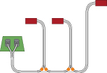
Figure 3-112.
Dual-conductor, white insulated wire can be used to connect the terminals on the alarm control box with magnetic sensors (shown in dark red). Because the sensors must be in series, the wire is cut and joined at positions marked with orange dots.
Figure 3-113 shows the same network as you might actually install it in a situation where you have two windows and a door. The blue rectangles are the magnetic modules that activate the switch modules.
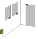
Figure 3-113.
In an installation involving two windows and a door, the magnetic components of the sensors (blue rectangles) could be placed as shown, while the switches (dark red) are located alongside them.
You’ll need a large quantity of wire, obviously. The type of white, stranded wire that is sold for doorbells or furnace thermostats is good. Typically, it is 20-gauge or larger.
After you install all the switches, clip your meter leads to the wires that would normally attach to the alarm box. Set your meter to test continuity, and open each window or door, one at a time, to check whether you’re breaking the continuity. If everything is OK, attach the alarm wires to the binding posts on your project box.
Now deal with the power supply. Use your AC adapter, set to 12 volts, hooked up to your type N power plug, or attach the power plug to a 12-volt alarm battery.
If you use a battery, be especially careful that the wire leading to the center terminal of your power plug is positive! A 12-volt battery can deliver substantial current, which can fry your components if you connect it the wrong way around. It would be a shame to destroy your entire project at the very last step.
The only remaining task is to label the switch, button, power socket, and binding posts on the alarm box. You know that the switch turns the power on and off, and the button tests the circuit and the noisemaker, but no one else knows, and you might want to allow a guest to use your alarm while you’re away. For that matter, months or years from now, you may forget some details. Will you remember that the power source for this unit should be 12 volts?
Labeling really is a good idea. But as you can see in Figure 3-114, I haven’t quite gotten around to it for the box that I built.
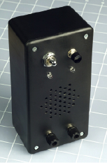
Figure 3-114.
The intrusion alarm completed and in its project box.
Conclusion
The alarm project has taken you through the basic steps that you will usually follow any time you develop something:
1.
Draw a schematic and make sure that you understand it.
2.
Modify it to fit the pattern of conductors on a breadboard.
3.
Install components on the breadboard and test the basic functions.
4.
Modify or enhance the circuit, and retest.
5.
Transfer to perforated board, test, and trace faults if necessary.
6.
Add switches, buttons, power jack, and plugs or sockets to connect the circuit with the outside world.
7.
Mount everything in a box (and add labeling).
While going through this sequence, I hope you’ve learned the basics of electricity, along with some simple electrical theory, and fundamentals about electronic components. This knowledge should enable you to move on to the much more powerful realm of integrated circuit—which I’ll cover in
Chapter 4
.
 Choose the Right Tubing
If you use heat-shrink tubing on 110v AC cord, as is being done in this experiment, make sure you use tubing that’s been rated for 110v use.
4.
Chips, Ahoy!
 Before I get into the fascinating topic of integrated circuit (IC) chips, I have to make a confession: some of the things I asked you to do in
Chapter 3
could have been done a bit more simply. Does this mean you have been wasting your time? No, I firmly believe that by building circuits with old-fashioned components—capacitors, resistors, and transistors—you acquire the best possible understanding of the principles of electronics. Still, you are going to find that integrated circuit chips, containing dozens, hundreds, or even thousands of transistor junctions, will enable some shortcuts.
Shopping List: Experiments 16 Through 24
Tools
The only new tool that I recommend using in conjunction with chips is a logic probe. This tells you whether a single pin on a chip has a high or low voltage, which can be helpful in figuring out what your circuit is doing. The probe has a memory function so that it will light its LED, and keep it lit, in response to a pulse that may have been too quick for the eye to see.
Search online and buy the cheapest logic probe you can find. I don’t have any specific brand recommendations. The one shown in Figure 4-1 is fairly typical.
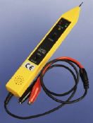
Figure 4-1.
A logic probe detects the high or low voltage on each pin of a chip, and reveals pulses that may occur too quickly for you to perceive them with the unaided eye.
Supplies
Integrated circuit chips
If you buy everything on this shopping list, and you bought basic parts such as resistors and capacitors that were listed previously, you should have everything you need for all the projects in this chapter.
As chips are quite cheap (currently around 50 cents apiece), I suggest you buy extras. This way, if you damage one, you’ll have some in reserve. You’ll also have a stock for future projects.
Please read the next section, “Fundamentals: Choosing chips,” before you begin chip-shopping. Chips should be easily obtainable from all the major electronics retail suppliers, and sometimes are found on eBay shops. Look in the appendix for a complete list of URLs.
Fundamentals
Choosing chips
Figure 4-2 shows what is often referred to as an integrated circuit (IC). The circuit is actually etched onto a tiny wafer or “chip” of silicon, embedded in a black plastic body, which is properly referred to as the “package.” Tiny wires inside the package link the circuit with the rows of pins on either side. Throughout this book, I will use the word “chip” to refer to the whole object, including its pins, as this is the most common usage.
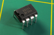
Figure 4-2.
An integrated circuit chip in Plastic Dual-Inline Pin package, abbreviated PDIP, or, more often, DIP.
The pins are mounted at intervals of 1/10 inch in two rows spaced 3/10 inch apart. This format is known as a Plastic Dual Inline Package, abbreviated PDIP, or, more often, just DIP. The chip in the photograph has four pins in each row; others may have many more. The first thing you need to know, when shopping for chips, is that you’ll only be using the DIP package. This book will not be featuring the more modern type, known as “surface-mount,” because they’re much smaller, more difficult to handle, and require special tools that are relatively expensive. Figure 4-3 shows a size comparison between a 14-pin DIP package and a 14-pin surface-mount package. Many surface-mount chips are even smaller than the one shown.
Just about every chip has a part number printed on it. In Figure 4-2, the part number is KA555. In Figure 4-3, the DIP chip’s part number is M74HC00B1, and the surface-mount chip is a 74LVC07AD. You can ignore the second line of numbers and/or letters on each chip, as they are not part of the part number.
Notice in Figure 4-3 that even though the chips look quite different from each other, they both have “74” in their part numbers. This is because both of them are members of the “7400” family of logic chips, which originally had part numbers from 7400 and upward (7400, 7401, 7402, 7403, and so on). Often they are now referred to as “74xx” chips, where “xx” includes all the members of the family. I’ll be using this family a lot, so you need to know how to buy them. I’ll give you some advice on that without going into details yet about what the chips actually do.
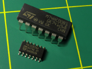
Figure 4-3.
The DIP chip, at the rear, has pins spaced 1/10 inch apart, suitable for insertion in a breadboard or perforated board. It can be soldered without special tools. The small-outline integrated circuit (SOIC) surface-mount chip (foreground) has solder tabs spaced at 1/20 inch. Other surface-mount chips have pins spaced at 1/40 inch or even less (these dimensions are often expressed in millimeters). Surface-mount chips are designed primarily for automated assembly and are difficult to work with manually. In this photo, the yellow lines are 1 inch apart to give you an idea of the scale.
Take a look at Figure 4-4, which shows how to interpret a typical part number in a 74xx family member. The initial letters identify the manufacturer (which you can ignore, as it really makes no difference for our purposes). Skip the letters until you get to the “74.” After that, you find two more letters, which are important. The 74xx family has evolved through many generations, and the letter(s) inserted after the “74” tell you which generation you’re dealing with. Some generations have included:
- 74L
- 74LS
- 74C
- 74HC
- 74AHC
And there are more. Generally speaking, subsequent generations tend to be faster or more versatile than previous generations. In this book, for reasons I’ll explain later, we are mostly using the HC generation.
Fundamentals
Choosing chips (continued)
After the letters identifying the generation, you’ll find two (sometimes more) numerals. These identify the specific function of the chip. You can ignore any remaining letters and numerals. Looking back at Figure 4-3, the DIP chip part number, M74HC00B1 tells you that it is a chip in the 74xx family, HC generation, with its function identified by numerals 00. The surface-mount chip number, 74LVC07AD, tells you that it is in the 74xx family, LVC generation, with function identified by numerals 07. For convenience we could refer to the first chip as a “74HC00” and the second chip as a “74LVC07” because, regardless of their different manufacturers and package sizes, the fundamental behavior of the circuit inside remains the same.
The purpose of this long explanation is to enable you to interpret catalog listings when you go chip shopping. You can search for “74HC00” and the online vendors are usually smart enough to show you appropriate chips from multiple manufacturers, even though there are letters preceding and following the term that you’re searched for.
Suppose a circuit requires a 74HC04 chip. If you search for “74HC04” on the website of a parts supplier, you may find versions such as the CD74HC04M96 by Texas Instruments, the 74HC04N by NXP Semiconductors, or MM74HC04N by Fairchild Semiconductor. Because they all have “74HC04” in the middle, any of them will work.
Just be careful that you buy the larger DIP-style package, not the surface-mount package. If the part number has an “N” on the end, you can be sure that it’s a DIP package. If there is no “N” on the end, it may or may not be a DIP package, and you will have to check a photo or additional description to make sure. If the part number begins with SS, SO, or TSS, it’s absolutely definitely surface-mount, and you don’t want it. Many catalogs show photographs of the chips to assist you in buying the right package style.
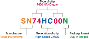
Figure 4-4.
Look for the chip family (74xx, in this case) with the correct generation (HC, in this case) embedded in the number. Make sure you buy the DIP version, not the surface-mount version. The manufacturer is unimportant.
Here’s your chip list:
- 555 Timer. STMicroelectronics SA555N, Fairchild NE555D, RadioShack TLC555, or similar. Do not get the “CMOS” version of this chip, or any fancy versions such as those of high precision. Buy the cheapest you can find. Quantity: 10. The chip in Figure 4-2 is a 555 timer.
- Logic chips types 74HC00, 74HC02, 74HC04, 74HC08, 74HC32, and 74HC86. Actual part numbers could be M74HC00B1, M74HC02B1, M74HC04B1, and so on, by STMicroelectronics, or SN74HC00N, SN74HC02N, SN74HC04N, and so on, by Texas Instruments. Any other manufacturers are acceptable.
- Remember, each part number should have “HC” in the middle of it, and you want the DIP or PDIP package, not surface-mount. Quantity of each: At least 4.
- 4026 Decade Counter (a chip that counts in tens). Texas Instruments CD4026BE or similar. Quantity: 4 (you’ll need 3, but because this is a CMOS chip sensitive to static electricity, you should have at least one in reserve). Any chip with “4026” in its part number should be OK.
- 74LS92 counter chip, 74LS06 open-collector inverter chip, and 74LS27 triple-input NOR chip. Quantity: 2 of each. Note the “LS” in these part numbers! There will be one experiment in which I want you to use the LS generation instead of the HC generation.