Make: Electronics (69 page)
Authors: Charles Platt

Theory
Sound, electricity, and sound (continued)
Somewhere along the way, we may want to record the sound and then replay it. But the principle remains the same. The hard part is designing the microphone, the amplifier, and the loudspeaker so that they reproduce the waveforms
accurately
at each step. It’s a significant challenge, which is why accurate sound reproduction can be elusive.
Time now to think about what happens inside the wire when it generates a magnetic field. Obviously, some of the power in the wire is being transformed into magnetic force. But just what exactly is going on?
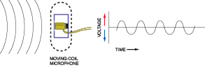
Figure 5-30.
Step 2: the pressure waves penetrate the perforated shell of a microphone and cause a diaphragm to vibrate in sympathy. The diaphragm has a coil attached to it. When the coil vibrates to and fro, a magnet at its center induces alternating current.
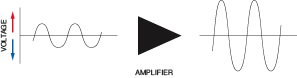
Figure 5-31.
Step 3: the tiny signals from the microphone pass through an amplifier, which enlarges their amplitude while retaining their frequency and the shape of their waveform.
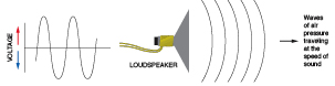
Figure 5-32.
Step 4: the amplified electrical signal is passed through a coil around the neck of a loudspeaker cone. The magnetic field induced by the current causes the cone to vibrate, reproducing the original sound.
Experiment 28: Making a Coil React
A capacitor will absorb some DC current until it is fully charged, at which point it blocks the flow. There’s another phenomenon that I haven’t mentioned so far, which is the exact opposite of capacitance. It’s known as
self-inductance
, and you find it in any coil of wire. Initially it blocks DC current (it reacts against it), but then its opposition gradually disappears. Here are a few definitions:
Resistance
Constrains current flow and drops voltage.
Capacitance
Allows current to flow initially and then blocks it. This behavior is properly known as capacitive reactance.
Self-Inductance
Blocks the flow of current initially and then allows it. This is also often referred to as
inductive reactance
. In fact, you may find the term “reactance” used as if it means the same thing, but since self-inductance is the correct term, I’ll be using it here.
In this experiment, you’ll see self-inductance in action.
You will need:
- LEDs, low-current type. Quantity: 2.
- Spool of hookup wire, 26-gauge, 100 feet. Quantity: 1.
- Resistor, 220Ω, rated 1/4 watt or higher. Quantity: 1.
- Capacitor, electrolytic, 2,000 μF or larger. Quantity: 1.
- SPST tactile switch. Quantity: 1.
Procedure
Take a look at the schematic in Figure 5-33. At first it may not make much sense. The curly symbol is a coil of wire—nothing more than that. So apparently the voltage will pass through the 220Ω resistor, and then through the coil, ignoring the two LEDs, because the coil obviously has a much lower resistance than either of them (and one of them is upside-down anyway).
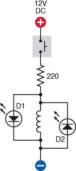
Figure 5-33.
In this demonstration of self-inductance, D1 and D2 are light-emitting diodes. When the switch is closed, D1 flashes briefly because the coil obstructs the initial flow of electricity. When the switch is opened, D2 flashes as the collapsing magnetic field induced by the coil releases another short burst of current.
Is that what will happen? Let’s find out. The coil can be a spool of 100 feet of 26-gauge (or smaller) hookup wire, although the spool of magnet wire listed in
Experiment 25
will work better, if you have that. Once again, you will need access to both ends of the wire, and if the inner end is inaccessible, you’ll need to rewind the coil, leaving the end sticking out.
Now that you have a coil, you can hook it up on your breadboard as shown in Figure 5-34, where the green circle is a tactile switch and the two circular red objects are LEDs. Make sure that you use low-current LEDs (otherwise, you may not see anything) and make sure that one of them is negative-side-up, positive-side-down and the other is positive-side-up, negative-side-down. Also, the 220Ω resistor should be rated at 1/4 watt or higher, if possible (see the following caution).
 Hot Resistors
You’ll be passing about 50mA through the 220Ω resistor, while the current is flowing. At 12 volts, this works out at 0.6 watts. If you use a 1/8-watt resistor, you will be overloading it, and it will get quite hot and may burn out. If you use a 1/4-watt resistor, it will still get hot, but is unlikely to burn out, as long as you don’t press the button for more than a second or two.
Don’t run the circuit without the coil of wire; you’ll be trying to pass more than 50mA through the LEDs.
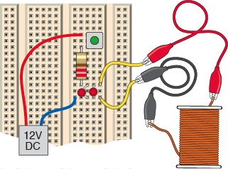
Figure 5-34.
The breadboarded version of the schematic in Figure 5-33 shows a simple way to set it up for a quick demo. The green button is a tactile switch. The two red LEDs should be placed so that the polarity of one is opposite to the polarity of the other.
When you press the button, one LED should flash briefly. When you release the button, the other LED should flash.
What’s happening here? The coil possesses self-inductance, which means that it reacts against any sudden change in the flow of electricity. First it fights it, and during that brief moment, it blocks most of the current. Consequently, the current looks for an alternative path and flows through D1, the lefthand LED in the schematic. (D2 doesn’t respond, because it can pass current only in the opposite direction.)
Meanwhile, the voltage pressure overcomes the coil’s self-inductance. When the self-inductance disappears, the resistance of the coil is no more than 10 ohms—so now the electricity flows mostly through the coil, and because the LED receives so little, it goes dark.
When you disconnect the power, the coil reacts again. It fights
any
sudden changes. After the flow of electricity stops, the coil stubbornly sustains it for a moment, because as the magnetic field collapses, it is turned back into electricity. This residual flow of current depletes itself through D2, the LED on the right.
In other words, the coil stores some energy in its magnetic field. This is similar to the way a capacitor stores energy between two metal plates, except that the coil blocks the current initially and then lets it build up, whereas the capacitor sucks up current initially, and then blocks it.
The more turns of wire you have in your coil, the more self-inductance the coil will have, causing your LEDs to flash more brightly.
Here’s one last variation on this experiment to test your understanding of electrical fundamentals. Remove the 220Ω resistor, and substitute a 1K resistor (to protect your LED from sustained current). Remove the coil, and substitute a very large capacitor—ideally, about 4,700 μF. (Be careful to get its polarity the right way around.) What will you see when you press the button? Note that you will have to hold it down for a couple of seconds to get a result. And what will you see when you release the button? Remember: the behavior of capacitance is opposite to the behavior of self-inductance.
Theory
Alternating current concepts
Here’s a simple thought experiment. Suppose you set up a 555 timer to send a stream of pulses through a coil. This is a primitive form of alternating current.
We might imagine that the self-inductance of the coil will interfere with the stream of pulses, depending how long each pulse is, and how much inductance the coil has. If the pulses are too short, the self-inductance of the coil will tend to block them. Maybe if we can time the pulses exactly right, they’ll synchronize with the time constant of the coil. In this way, we can “tune” a coil to allow a “frequency” to pass through it.
What happens if we substitute a capacitor? If the pulses are too long, compared with the time constant of the capacitor, it will tend to block them, because it will have enough time to become fully charged. But if the pulses are shorter, the capacitor can charge and discharge in rhythm with the pulses, and will seem to allow them through.
I don’t have space in this book to get deeply into alternating current. It’s a vast and complicated field where electricity behaves in strange and wonderful ways, and the mathematics that describe it can become quite challenging, involving differential equations and imaginary numbers. However, we can easily demonstrate the audio filtering effects of a loudspeaker and a coil.