Make: Electronics (73 page)
Authors: Charles Platt

Schematic
The output from the 555 timer is a square wave, so it already sounds quite “fuzzy,” but we can make it more intense to demonstrate the clipping principle. I’ve redrawn the whole circuit in Figure 5-55, as several components have changed. The principal alteration is the addition of two NPN transistors.
If you assemble this circuit on your breadboard, note carefully that the 33K and 10K resistors at the bottom of the amplifier chip have been removed, and there’s now just an 820Ω resistor in that location. The bottom of the adjacent 0.22 μF capacitor is still the input point for the amplifier, and if you follow the connection around to the middle of the schematic, you’ll find it leading to a 100K potentiometer. This is your “fuzz adjuster.”
The two NPN transistors are arranged so that the one on the left receives output from the 555 timer. This signal controls the flow of electricity through the transistor from a 33K resistor. This flow, in turn, controls the base of the righthand transistor, and the flow of current through that is what ultimately controls the amplifier.
When you power up the circuit, use the 100K potentiometer attached to the 555 timer to adjust the frequency (as before) and crank the “fuzz adjuster” potentiometer to hear how it adds increasing “bite” to the sound until ultimately it becomes pure noise.
The two transistors act as amplifiers. Of course, we didn’t need them for that purpose—the input level for the amplifier chip was already more than adequate. The purpose of the lefthand transistor is simply to overload the righthand transistor, to create the “fuzz” effect. And when you turn up the output from the transistors with the “fuzz adjuster,” eventually they overload the input of the amplifier chip, creating even more distortion.
If you want to tweak the output, try substituting different values for the 1K resistor and the 1 μF capacitor that are positioned between the emitter of the righthand transistor and the negative side of the power supply. A larger resistor should overload the transistor less. Different capacitor values should make the sound more or less harsh.
You can find literally thousands of schematics online for gadgets to modify guitar sound. The circuit I’ve included here is one of the most primitive. If you want something more versatile, you should search for “stomp box schematics” and see what you can find.
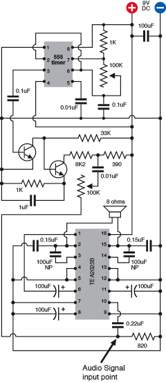
Figure 5-55.
For a quick demo of clipping, insert a couple of transistors between the output from the 555 timer and the input of the amplifier chip. One transistor overdrives the other, so that when you adjust the potentiometer at the center of the circuit, you hear an increasingly harsh, distorted sound.
Background
Stomp-box origins
The Ventures recorded the first single to use a fuzz box, titled “The 2,000 Pound Bee,” in 1962. Truly one of the most awful instrumentals ever made, it used distortion merely as a gimmick and must have discouraged other musicians from taking the concept seriously.
Ray Davies of the Kinks was the first to embody distortion as an integral part of his music. Davies did it initially by plugging the output from one amp into the input of another, supposedly during the recording of his hit “You Really Got Me.” This overloaded the input and created clipping—the basic fuzz concept. From there it was a short step to Keith Richards using a Gibson Maestro Fuzz-Tone when the Rolling Stones recorded “(I Can’t Get No) Satisfaction” in 1965.
Today, you can find thousands of advocates promoting as many different mythologies about “ideal” distortion. In Figure 5-56, I’ve included a schematic from Flavio Dellepiane, a circuit designer in Italy who gives away his work (with a little help from Google AdSense) at
http://www.redcircuits.com
. Dellepiane is self-taught, having gained much of his knowledge from electronics magazines such as the British
Wireless World
. In his fuzz circuit, he uses a very high-gain amplifier consisting of three field-effect transistors (FETs), which closely imitate the rounded square-wave typical of an overdriven tube amp.
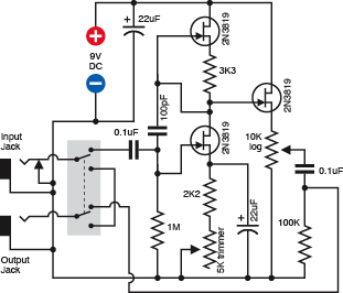
Figure 5-56.
This circuit designed by Flavio Dellepiane uses three transistors to simulate the kind of distortion that used to be created by overloading the input of a tube amplifier.
Dellepiane offers dozens more schematics on his site, developed and tested with a dual-trace oscilloscope, low-distortion sinewave oscillator (so that he can give audio devices a “clean” input), distortion meter, and precision audio volt meter. This last item, and the oscillator, were built from his own designs, and he gives away their schematics, too. Thus his site provides one-stop shopping for home-audio electronics hobbyists in search of a self-administered education.
Before fuzz, there was tremolo. A lot of people confuse this with vibrato, so let’s clarify that distinction right now:
- Vibrato applied to a note makes the frequency waver up and down, as if a guitarist is bending the strings.
- Tremolo applied to a note makes its volume fluctuate, as if someone is turning the volume control of a guitar up and down very quickly.
Background
Stomp-box origins (continued)
Harry DeArmond sold the first tremolo box, which he named the Trem-Trol. It looked like an antique portable radio, with two dials on the front and a carrying handle on top. Perhaps in an effort to cut costs, DeArmond didn’t use any electronic components. His steam-punkish Trem-Trol contained a motor fitted with a tapered shaft, with a rubber wheel pressing against it. The speed of the wheel varied when you turned a knob to reposition the wheel up and down the shaft. The wheel, in turn, cranked a little capsule of “hydro-fluid,” in which two wires were immersed, carrying the audio signal. As the capsule rocked to and fro, the fluid sloshed from side to side, and the resistance between the electrodes fluctuated. This modulated the audio output.
Today, Trem-Trols are an antique collectible. When industrial designer Dan Formosa acquired one, he put pictures online at
http://www.danformosa.com/dearmond.html
. And Johann Burkard has posted an MP3 of his DeArmond Trem-Trol so you can actually hear it:
http://johannburkard.de/blog/music/effects/DeArmond-Tremolo-Control-clip.html
.
The idea of a mechanical source for electronic sound mods didn’t end there. The original Hammond organs derived their unique, rich sound from a set of toothed wheels turned by a motor. Each wheel created a fluctuating inductance in a sensor like the record head from a cassette player.
It’s easy to think of other possibilities for motor-driven stomp boxes. Going back to tremolo: imagine a transparent disc masked with black paint, except for a circular stripe that tapers at each end. While the disc rotates, if you shine a bright LED through the transparent stripe toward a light-dependent resistor, you would have the basis for a tremolo device. You could even create never-before-heard tremolo effects by swapping discs with different stripe patterns. Figures 5-57 and 5-58 show the kind of thing I have in mind. For a real fabrication challenge, how about an automatic disc changer?
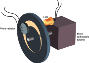
Figure 5-57.
Although electromechanical audio devices are obsolete now, some unexplored possibilities still exist. This design could create various tremolo effects, if anyone had the patience to build it.

Figure 5-58.
Different stripe patterns could be used in conjunction with the imaginary electromechanical device in Figure 5-57 to create various tremolo effects.
Today’s guitarists can choose from a smorgasbord of effects, all of which can be home-built using plans available online. For reference, try these special-interest books:
- Analog Man’s Guide to Vintage Effects
by Tom Hughes (For Musicians Only Publishing, 2004). This is a guide to every vintage stomp box and pedal you can imagine. - How to Modify Effect Pedals for Guitar and Bass
by Brian Wampler (Custom Books Publishing, 2007). This is an extremely detailed guide for beginners with little or no prior knowledge. Currently it is available only by download, from sites such as
http://www.openlibrary.org
, but you may be able to find the previous printed edition from secondhand sellers, if you search for the title and the author.
Of course, you can always take a shortcut by laying down a couple hundred dollars for an off-the-shelf item such as a Boss ME-20, which uses digital processing to emulate distortion, metal, fuzz, chorus, phaser, flanger, tremolo, delay, reverb, and several more, all in one convenient multi-pedal package. Purists, of course, will claim that it “doesn’t sound the same,” but maybe that’s not the point. Some of us simply can’t get no satisfaction until we build our own stomp box and then tweak it, in search of a sound that doesn’t come off-the-shelf and is wholly our own.
Experiment 31: One Radio, No Solder,
No Power
Time now to go back one more time to inductance and capacitance, and demonstrate an application which also makes use of the way that waveforms can be added to each other. I want to show you how a simple circuit with no power supply at all can receive AM radio signals and make them audible. This is often known as a crystal radio, because the circuit includes a germanium diode, which has a crystal inside it. The idea dates back to the dawn of radio, but if you’ve never tried it, you’ve missed an experience that is truly magical.
You will need:
- Rigid cylindrical object, such as a vitamin bottle. Quantity: 1.
- 22-gauge hookup wire, solid-core. Quantity: 60 feet.
- 16-gauge wire, stranded. Quantity: 100 feet.
- Polypropylene rope (“poly rope”) or nylon rope. Quantity: 10 feet.
- Germanium diode. Quantity: 1.
- High-impedance headphone. Quantity: 1.