Make: Electronics (84 page)
Authors: Charles Platt

To download your programming instructions into the chip, first you’ll type the instructions on a computer, and then you’ll feed them through a cable into the PICAXE memory. So you’ll need to buy a cable, and you’ll need software to help you to write the program.
You can use the PICAXE with a serial cable, but I don’t recommend it. The old RS-232 serial communications standard on PCs is pretty much obsolete, and PICAXE has recognized this by offering a USB cable (which contains a serial converter inside its plug). The USB cable is a little more expensive, but is also simpler and compatible with Apple computers. From any of the U.S. distributors, buy USB cable part AXE027, also sold as part PGM-08312 by
http://www.sparkfun.com
(quantity: 1). The cable is shown in Figure 5-125.
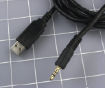
Figure 5-125.
The USB download cable made for use with the PICAXE terminates in a 3.5-mm audio plug. This should not be inserted in any audio device. It establishes a serial connection with a computer, allowing program code to be downloaded into the chip.
To write your software and send it down the wire to the chip, the PICAXE Programming Editor is the tool of choice. It comes in only a Windows version. For those who prefer Mac OS or Linux, you can get a free download of another piece of software known as AXEpad, which has fewer features, but will do the job. All the downloadable software is freely available from
http://www.rev-ed.co.uk/picaxe/software.htm
.
Finally, you need a 3.5-mm stereo audio socket with solder connections. The reason for this is that the manufacturers of the PICAXE have used a stereo audio plug on the free end of their USB cable, and you have to be able to plug it into something. The PICAXE breadboard adapter, SparkFun stock number DEV-08331, contains the necessary stereo socket in addition to a few other little items. Quantity: 1. See Figure 5-126.
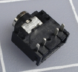
Figure 5-126.
Closeup of the 3.5-mm stereo socket that is used with the USB download cable.
Oddly enough, the USB cable is the most expensive item on the list, because of the electronics hidden inside it.
Software Installation and Setup
Now you have to go through a setup procedure. There is no way around this. Here is what you will be doing:
1.
Install a driver so that your computer will recognize the special USB cable.
2.
Install the Programming Editor software (or AXEpad for Mac/Linux) so that your computer will help you to write programs and then download them into the chip.
3.
Mount the PICAXE on your breadboard and add the socket to receive downloads.
These steps are explained in the following sections.
The USB driver
Fair warning: If you go to the PICAXE website and try to use its search function, it probably won’t find what you want. Search for “USB Driver,” for instance, and it will pretend it has never heard of such a thing.
The PICAXE home page also has irritating drop-down menus that tend to disappear just when you’re about to click on them, but at the time of writing, you can bypass these issues by going straight to the Software Downloads section at
http://www.rev-ed.co.uk/picaxe/software.htm
.
Scroll down past all the software until you get to Additional Resources. Look for the AXE027 PICAXE USB Download Cable. At first glance, it looks as if they want to sell you a cable, but in fact this is the list of drivers. Double-click the one appropriate to your computer, and choose a destination on your computer for the download—a place where you will find it easily, such as your desktop.
Be careful not to download the driver for the USB010 USB-Serial adapter by mistake. The USB-Serial adapter is something else entirely.
The download will leave you with a zipped file folder. You will have to unzip it. On Windows XP, right-click the folder and choose “Extract all.” View the extracted files and you will find a PDF installation guide. Linux and Mac users can find instructions currently stashed at
http://www.rev-ed.co.uk/docs/AXE027.pdf
.
When installing the driver on a Windows platform, here are a few tips to minimize your exasperation level:
1.
Remember, the special USB cable contains some electronics. It is not just a cable, but a device designed for interacting with a PICAXE chip.
Don’t try to use it for anything else!
2.
You have to plug the cable into a USB port
before
you install the driver, because your computer will need to verify that the driver matches the cable.
3.
You must not attach the PICAXE to the other end of the cable until
after
you have installed the driver.
4.
Every USB port on your computer has a separate identity. Whichever one you choose when you first plug in the cable, you should use that port
every time in the future
. Otherwise, you will have to repeat the process of telling your computer what the cable is.
5.
Bearing in mind Tip #4, you should avoid using the cable in a standalone USB hub.
6.
The cable is fooling the PICAXE into thinking that it’s talking to a serial port on your computer. Those “communication” ports are known as COM1, COM2, COM3, or COM4. When you install the driver, the installer will choose one of those COM ports for you, and later you will have to know which one it is. The PDF guide should help you through this procedure. Unfortunately, you cannot skip it.
The Programming Editor software
If you have come this far, you’re ready for the next big step, which is much easier. You need the PICAXE Programming Editor, available for free on the Software Downloads web page where you found the USB driver. (If you are using a Mac or Linux, you will need AXEpad, which is on the same web page.)
Downloading and installing the Programming Editor should be simple and painless. Once you have done that, you should find that it has placed a shortcut on your desktop. Double-click it, go to View→Options, and in the window that opens (shown in Figure 5-127), click the Serial Port tab. You should see a dialog box like the one in Figure 5-128. Now make sure that the Programming Editor is looking at the same COM port that was chosen by the USB driver. Otherwise, the Programming Editor won’t know where to find your PICAXE chip.
In the Programming Editor, go to View→Options and click the Mode tab, then click the button to select the 08M chip.
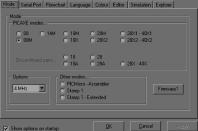
Figure 5-127.
This screenshot shows the options window of the PICAXE Program Editor, which you must use to select the type of chip that you intend to program (in our case, the 08M).
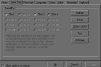
Figure 5-128.
Another screenshot of the options window shows the second essential choice that you must make: selection of the COM port that the installer chose on your computer.
Are we having fun yet? Obviously not, but you’re through with software hassles for the time being. The last step before you’re ready to use the PICAXE is to mount it, and its socket, on your breadboard.
Setting up the hardware
The PICAXE 08M looks like a 555 timer. (Other chips in the PICAXE range have more pins and more features.) It requires a properly regulated 5 volts, just like the logic chips you dealt with previously. In fact, the PICAXE people are rather emphatic about protecting it from voltage spikes. They want you to use two capacitors (one 100 μF, one 0.1 μF) on either side of an LM7805 regulator. This seems like overkill, but the PICAXE is more inconvenient to replace than a 555 timer. You certainly can’t run down to RadioShack to buy one. So let’s do what the manufacturer says, just in case, and set up a breadboard as shown in Figures 5-129 and 5-130.
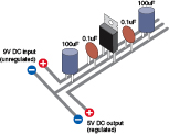
Figure 5-129.
PICAXE documentation specifies a 100 μF and 0.1 μF capacitor on the input side of a 5-volt regulator, and a similar pair of capacitors on its output side. On a breadboard, they can be arrayed like this.
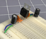
Figure 5-130.
The actual components for power regulation, applied to a breadboard, delivering 5 volts (positive and negative) down each side.
