Make: Electronics (83 page)
Authors: Charles Platt

The ULN2001A is only an amplification device, so you have to precede it with a counter that runs from 1 to 4 and then repeats. You can stick with your 555 timers, as you’ve already assembled them, or substitute almost any CMOS octal or decade counter that sends its output pulses to a series of pins. Just use the output from the fifth pin as the “carry” output to restart the counting sequence. I suggest a CMOS counter simply because it will run on 12 volts, so you can use the same power supply that suits your stepper motors.
If you switch to CMOS counters, you will still need a pair of 555 timers sending pulses to the counters. The timers will be free-running in astable mode, and your photoresistors will control their speed. Figure 5-120 shows the configuration.
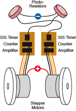
Figure 5-120.
A more efficient way to drive the motors is to use just one timer to set the speed of each, with a counter and amplifier (such as a Darlington array chip) sending the pulses down the wires. The principle is still the same, though.
One last item: you’ll need a 12-volt battery. You can of course put eight AA cells together, but I think you should consider a rechargeable pack from a source such as
http://www.all-battery.com
, which has a section entirely devoted to “robot batteries.”
If you put it all together, you should find that when you place your robot cart in a very dimly lit room, it will turn toward the beam from a bright, well-focused flashlight. To get reliable results, you may have to recess each of the photoresistors in little tubes, so that they receive much more light when they face your flashlight than when they face away from it. Figure 5-121 is a 3D rendering of the concept.
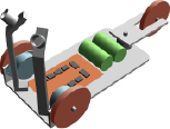
Figure 5-121.
This 3D rendering shows a possible configuration of the light-seeking cart, with two photoresistors enclosed in small tubes to restrict their response to light.
Another idea is to rewire your cart so that it actually runs away from the light. Can you imagine how this might be done?
Just one more thought: if you use infrared photoresistors, you can control your cart with beams from infrared LEDs, in normal room lighting. If you and a couple of friends all have infrared transmitters, you can get your cart to run from one of you to the next, like an obedient dog.
This takes us about as far as I’m going to go into robotics. I urge you to check out the sites online if you want to pursue the topic further. You can also buy a wide variety of robot kits, although of course I feel that it’s more fun to invent or develop things for yourself.
All that’s left now is to perform one last introduction: to a device that should make your life much easier, even though the device is much more complicated than anything we have dealt with so far.
Experiment 34: Hardware Meets Software
Throughout this book, in accordance with the goal of
learning by discovery
, I have asked you to do an experiment first, after which I’ve suggested the general principles and ideas that we can learn from it. I now have to change that policy, because the next experiment involves so much setup that it’s only fair to tell you what to expect before you begin the preparations.
We are about to enter the realm of controller chips, often known as MCUs, which is an acronym for micro controller unit. An MCU contains some flash memory, which stores a program that you write yourself. The flash memory is like the memory in a portable media player, or the memory card that you use in a digital camera. It needs no electricity to power it. In addition, the chip has a processor which carries out the instructions in your program. It has RAM to store the values of variables on a temporary basis, and ROM, which tells it how to perform tasks such as sensing a varying voltage input and converting it into digital form for internal use. It also contains an accurate oscillator, so that it can keep track of time. Put it all together, and it’s a tiny computer that you can buy for under $5.
Let’s suppose that you have a greenhouse where the temperature must never fall below freezing. You set up a temperature sensor, and you have two different heaters. You want to switch on the first heater if the temperature falls below 38° Fahrenheit. But if, for some reason, that heater is broken, you want to switch on the second, backup heater when the temperature goes below 36° Fahrenheit.
Programming a MCU to take care of this can be very simple indeed. You could even add extra features, such as a second temperature sensor, just in case the first one fails, and you could tell the chip to use whichever sensor gives a lower reading.
Another application for a MCU would be in a fairly elaborate security system. The chip could monitor the status of various intrusion sensors, and can take various preprogrammed steps, depending on the sensors’ status. You could include delay intervals, too.
Many MCUs have additional useful features built in, such as the ability to control servo motors that turn to a specific angle in response to a stream of pulses. Servos are widely used in radio-controlled model boats, airplanes, and hobby robotics.
Perhaps you are now wondering why, if MCUs can do all this, haven’t we been using them all along? Why did I spend so much time describing the development of an alarm system using discrete components, if one chip could have done everything?
There are three answers:
1.
MCUs cannot do everything. They need other components to help them interact with the world, such as transistors, relays, sensors, and amplifiers. You need to know how those things work, so that you can make intelligent use of them.
2.
MCUs can introduce their own kinds of problems and errors, associated with using software in addition to hardware. I’ll have more to say about this later.
3.
MCUs have limits and restrictions, most obviously their requirement for a 5-volt regulated power supply, and their inability to source or sink much current from each pin. They also demand that you learn a programming language (which differs from one brand of MCU to the next). And to get the program into the chip, you have to be able to plug it into a computer and do a download, which is not always convenient.
In this experiment, you’ll learn how to write a program for a small and simple MCU, and you’ll transfer the program into it and see how it works.
Background
Origins of programmable chips
In factories and laboratories, many procedures are repetitive. A flow sensor may have to control a heating element. A motion sensor may have to adjust the speed of a motor. Microcontrollers are perfect for this kind of routine task.
A company named General Instrument introduced an early line of MCUs in 1976, and called them PICs, meaning Programmable Intelligent Computer—or Programmable Interface Controller, depending which source you believe. General Instrument sold the brand to another company named Microchip Technology, which owns it today.
“PIC” is trademarked, but is sometimes used as if it’s a generic term, like Scotch tape. In this book, I’ve chosen a range of controllers based on the PIC architecture. They are licensed by a British company named Revolution Education Ltd., which calls its range of chips the PICAXE, for no apparent logical reason other than that it sounds cool.
I like these microcontrollers because they were developed originally as an educational tool and because they are very easy to use. They’re cheap, and some of them are quite powerful. Despite their odd name, I think they’re the best way to get acquainted with the core concepts of MCUs.
After you play with the PICAXE, if you want to go farther into MCUs, I suggest the BASIC Stamp (which uses a very similar language, but with additional powerful commands) and the very popular Arduino (which is a more recent design, packed with powerful features, but requires you to learn a variant of C language to program it). I’ll say more about these chips later.
If you search for “picaxe” on Wikipedia, you’ll find an excellent introduction to all the various features. In fact, I think it’s a clearer overview than you’ll get from the PICAXE website.
Supplies
Figure 5-122 shows some of the chips in the PICAXE range. I’ll be telling you how to use the smallest—the 08M—which costs less than $5 and is cheaper than any other MCU that I’ve found. It has only 256 bytes of memory to store a program (not gigabytes, megabytes, or kilobytes, just 256 bytes!), but you’ll be surprised how many possibilities this amount allows for. Figure 5-123 shows a closeup of the 08M with its legs safely embedded in a piece of conductive foam.
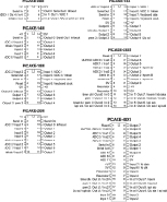
Figure 5-122.
A page from the PICAXE catalog lists only some of the chips that are available. What began as an educational aid has become a useful prototyping tool.
In the United States, there are three distributors of this chip:
I like P. H. Anderson for its grass-roots hobbyist approach, and they have good prices if you want to buy multiple chips. But SparkFun Electronics offers other associated products that you may find interesting.
All the distributors will want to sell you “starter kits,” such as the one in Figure 5-124, perhaps because the PICAXE itself is so cheap that it doesn’t offer much of a profit margin. Still, for our purposes, you should buy the chip as a standalone item. And buy two of them, just in case you damage one (for example, by connecting voltage to it incorrectly).
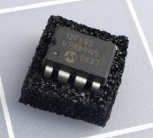
Figure 5-123.
When supplied by one of its American distributors, a PICAXE 08M arrives embedded in a little square of conductive foam. The chip is the same size as a 555 timer but has the power of a tiny computer.
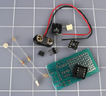
Figure 5-124.
A typical PICAXE kit includes a printed circuit board, which you may not really need, and some other not-entirely-essential items. But the 3.5-mm stereo jack socket (top, center) is absolutely necessary.
