Make: Electronics (80 page)
Authors: Charles Platt

Theory
Calculating voltage drop
Another fact that you often need to know is how much of a voltage drop a particular length of wire will introduce in a circuit. If you want to get maximum power from a motor, you don’t want to lose too much voltage in the wires that go to and from the motor.
Voltage drop is tricky, because it depends not only on the wire, but also on how heavily the circuit is loaded. Suppose that you are using 100 feet of 22-gauge wire, which has a resistance of about 1.5 ohms. If you attach it to a 12-volt battery and drive an LED and a series resistor offering a total effective resistance of about 1,200 ohms, the resistance of the wire is trivial by comparison. According to Ohm’s Law:
amps = volts / ohms
so the current through the circuit is only about 10mA.
Again, by Ohm’s Law:
volts = ohms × amps
so the wire with resistance of 1.5 ohms imposes a voltage drop of 1.5 × 0.01 = 0.015 volts.
Now suppose you’re running a motor. The coils in the motor create impedance, rather than resistance, but still if we measure how much current is going through the circuit, we can establish its effective resistance. Suppose the current is 1 amp. Repeating the second calculation:
volts = ohms × amps
So the voltage drop in the wire is now 1.5 × 1 = 1.5 volts! This is illustrated in Figure 5-104.
Bearing these factors in mind, I have compiled a table for you. I’ve rounded the numbers to just two digits, as variations in the wire that you use make any pretense of greater accuracy unrealistic.
To use this table, you need to know how much current is passing through your circuit. You can calculate it (by adding up all the resistances and dividing it into the voltage that you are applying) or you can simply measure the current with a meter. Just make sure that your units are consistent (all in ohms, amps, and volts, or milliohms, milliamps, and millivolts).
In the table, I have arbitrarily assumed a length of 10 feet of wire. Naturally you will have to make allowances for the actual length of wire in your circuit. The shorter the wire, the less the loss will be. A circuit with only 5 feet of wire, and the same amperage and voltage, will suffer half of the percentage loss shown in the table. A circuit with 15 feet of wire, and the same amperage and voltage, will suffer 1.5 times the percentage loss. So, to use the table:
1.
Divide your length of wire by 10. (Make sure that you measure the length in feet.)
2.
Use the result to multiply the number in the table.
The table also arbitrarily assumes that you have a 12-volt supply. Again, you will have to make allowances if you are using a different voltage. So, to use the table:
1.
Divide 12 by the actual voltage of your power supply.
2.
Use the result to multiply the number in the table.
I can summarize those two steps like this:
Percent voltage lost = P × (12 / V) × (L / 10)
where P is the number from the table, V is your power-supply voltage, and L is the length of your wire.
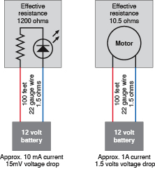
Figure 5-104.
The voltage drop imposed by wiring will depend on the current and the resistance in the circuit. The drop will be greatest when the resistance of the circuit is low and the amperage is high.
Theory
Calculating voltage drop (continued)
This table shows the percent voltage lost in a circuit with 10-foot wire at 12 volts.
Wire Gauge | Amperes | |||||||||
| 1 | 2 | 3 | 4 | 5 | 6 | 7 | 8 | 9 | 10 |
10 | 0.08 | 0 | 0 | 0 | 0 | 0 | 0 | 0 | 0 | 0 |
12 | 0.13 | 0 | 0 | 0 | 0 | 0 | 0 | 0 | 0 | 0 |
14 | 0.21 | 0 | 0 | 0 | 0 | 0 | 0 | 0 | 0 | 0 |
16 | 0.33 | 0 | 0 | 0 | 0 | 0 | 0 | 0 | 0 | 0 |
18 | 0.53 | 0 | 0 | 0 | 0 | 0 | 0 | 0 | 0 | 0 |
20 | 0.85 | 0 | 0 | 0 | 0 | 0 | 0 | 0 | 0 | 0 |
22 | 1.3 | 0 | 0 | 0 | 0 | 0 | 0 | 11 | 12 | 13 |
24 | 2.1 | 0 | 0 | 0 | 11 | 13 | 15 | 17 | 19 | 21 |
26 | 3.4 | 0 | 10 | 14 | 17 | 20 | 24 | 27 | 31 | 34 |
28 | 5.4 | 11 | 16 | 22 | 27 | 32 | 38 | 43 | 49 | 54 |
30 | 8.6 | 17 | 26 | 34 | 43 | 52 | 60 | 69 | 77 | 86 |
Remember, though, that the wire resistance will be higher if you are using stranded copper wire or tinned copper wire, and this will increase the percentage of voltage lost.
Experiment 33: Moving in Steps
Time now to build something more sophisticated: a cart that orients itself toward a light source. I’m going to tell you all you need to get started on this project, but this time I won’t go all the way to the end in exhaustive detail. I want you to get into the habit of figuring out the details, improving on plans, and eventually inventing things for yourself.
You will need:
- 555 timers. Quantity: 8.
- Trimmer potentiometer, 2K linear. Quantity: 2.
- LEDs. Quantity: 4. If you get tired of using series resistors to protect LEDs in a 12-volt circuit, consider buying 12-volt LEDs such as Chicago Miniature 606-4302H1-12V, which contain their own resistors built in. However, the schematic in Figure 5-108 assumes that you will use regular 2V or 2.5V LEDs.
- Stepper motor: Unipolar, four-phase, 12-volt. Parallax 27964 or similar, consuming 100mA maximum. Quantity: 2.
- Photoresistors, ideally 500 to 3,000Ω range. Quantity: 2.
- ULN2001A or ULN2003A Darlington arrays by STMicroelectronics. Quantity: 2.
- CMOS octal or decade counter. Quantity: 2.
- Various resistors and capacitors.
Exploring Your Motor
I’ve specified a unipolar, four-phase, 12-volt motor because this is a very common type. A typical sample is shown in Figure 5-105. If you can’t easily find the one that I’ve listed, you should feel safe in buying any other that has the same generic description. “Unipolar” means that you don’t have to switch the power supply from positive to negative and back to positive again, to run the motor. Four-phase means that the pulses that run the motor must be applied in sequence to four separate wires. Because you will be running your motor directly from 555 timers, the lower its power consumption, the better.
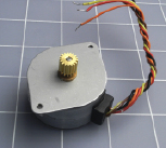
Figure 5-105.
A typical stepper motor. The shaft rotates in steps when negative pulses are applied to four of the wires in sequence, the fifth wire being common-positive.
First, though, we can apply voltage to the motor without using any other components at all. Most likely it will have five wires already attached, with the ends stripped and tinned, so that you can easily insert them into holes in a breadboard, as shown in Figure 5-106. Check the data sheet for your motor; you should find that four of the wires are used to energize the motor and turn it in steps, while the fifth is the common connection. In many cases, the common connection should be hooked to the positive side of your power supply, while you apply negative voltage to the other four wires in sequence, one step at a time.