Moon Lander: How We Developed the Apollo Lunar Module (13 page)
Read Moon Lander: How We Developed the Apollo Lunar Module Online
Authors: Thomas J. Kelly
Tags: #Science, #Physics, #Astrophysics, #Technology & Engineering, #History

Best of all, the standing position moved the pilot’s eyes closer to the window, yielding the same viewing angles with much less glass area. We discussed various approaches to window geometry and agreed to start with a flat window that would provide the same view angles. Will Bischoff and Len Paulsrud joined the discussion and were asked to prepare structural design arrangements for the new crew compartment. Harms and Paulsrud constructed a full-sized foam-board mockup of the crew compartment to work out the combined structural design and crew provisions concepts.
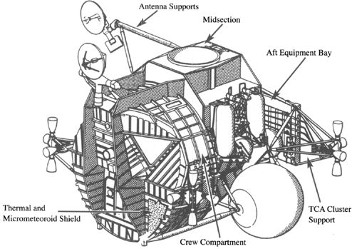
The lunar module’s ascent stage. (Courtesy Northrop/Grumman Corporation) (
Illustration credit 5.2
)
I visited the rudimentary cabin mockup every day as the LM crew compartment that was ultimately built and flown took shape. Computer-aided studies of window geometry led us to tilt the plane of the windows downward and outward, resulting in a small, flat, triangular pair of windows that provided greater vision angles than the original large curved windows. To provide structural rigidity to the flat, pressurized front face of the crew compartment, a pair of deep external beams were added on either side of the forward hatch. A cylindrical protrusion into the cabin behind the flight station was required to accommodate the upper end of the ascent rocket engine, but there was volume behind and on either side of this obstruction for crew equipment, spacesuit and backpack stowage and for rest stations equipped with mesh hammocks. A small rectangular window was added overhead to aid the docking maneuver.
As soon as we shared the new concept with NASA it was enthusiastically received, and a visit from the LM liaison astronaut Donn Eisele further confirmed the acceptability of this approach. (In
Chariots for Apollo
, NASA historians C. G. Brooks, et al. credit NASA crew systems engineers George C. Franklin and Louie G. Richard with originating the idea of eliminating LM’s seats. My recollection is that the Grumman team started it, but in any event the NASA and Grumman crew systems teams worked so closely and cooperatively together that the credit is properly shared.) We released the design for the wooden M-1 mockup to be reviewed by NASA in September 1963. An important piece of the LM design puzzle had been put into place.
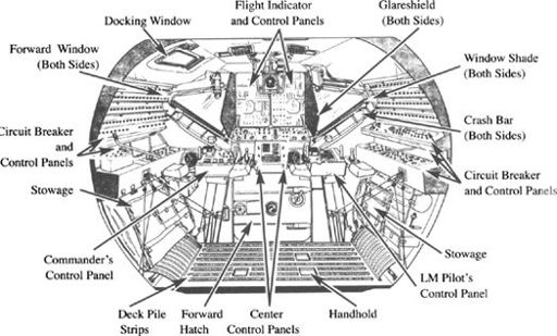
The lunar module’s crew compartment and flight station. (Courtesy Northrop/Grumman Corporation) (
Illustration credit 5.3
)
Mechanical Systems and Explosive Devices
Another design area that required both innovation and careful attention to details was mechanical systems, including the landing gear, docking mechanisms, hatches, equipment stowage compartments and miscellaneous mechanical devices, and explosive devices for stage separation and propulsion-system activation. This was the province of Virgilio “
Jiggs
” Sturiale, the Mechanical Design section head, and his deputy Marcello “Marcy” Romanelli. This talented pair had many years of experience designing, building, and testing the complex mechanisms required in Grumman’s carrier-based aircraft, especially the flight-control mechanisms (for ailerons, flaps, rudders, and elevators), retractable landing gear, wing-fold mechanisms, ejection seats,
canopy releases, and tailhook extension and retraction devices. The challenges facing them on the LM were different but no more demanding than the many critical devices to which navy pilots entrusted their lives on every flight of a Grumman aircraft.
Our proposed fixed landing gear contained a major design innovation that, although greatly altered in specifics, carried through into the flight LMs. Concerned about the weight and potential for leakage of fluid into space from conventional hydraulic or pneumatic energy absorbers, I insisted on a dry version. In the proposal we thought it would be some form of molded elastic compound, but as the design evolved into an extendible four-legged landing gear a new energy absorbing material had to be developed to dissipate sufficient energy in a short stroke. Jiggs and Marcy searched for suitable materials and came up with crushable aluminum honeycomb. Hexcell had developed aluminum honeycomb as a lightweight, rigid, high-strength filler material for aircraft control surfaces, particularly the trailing edges, which typically taper down to end in a point. Hexcell was exploring new uses for its material and believed that it could be configured as a highly efficient energy absorber for the LM landing gear. Marcy designed some test struts for which Hexcell fabricated cylindrical slugs of crushable honeycomb. The initial test results were very promising: they indicated that the amount of energy that could be absorbed by a three- to four-inch diameter honeycomb cylinder with a crushable stroke of twenty-four to thirty-six inches was in the range required by the LM’s landing conditions. I asked Jiggs to proceed with the landing-gear design using this approach, and we authorized Hexcell to conduct a development program to characterize and optimize crushable honeycomb for energy absorption.
The landing gear Jiggs and Marcy designed was as simple as possible, given the design constraints. It was spring-loaded extensible, released by explosively actuated strap cutters (uplocks), and locked into place by redundant mechanical downlocks on each landing-gear strut assembly. There was no requirement to retract the gear once extended. In the final design the main compression strut on each of the four legs had a stroke of thirty-two inches and the footpad was thirty-seven inches in diameter, a compromise value given the unknowns of the lunar surface that we felt would ensure minimal penetration of the LM into a low load-bearing strength surface.
There were conflicting opinions from the experts regarding the nature of the lunar surface even as LM was being designed. Radar echoes from the Moon hinted at a possible porous surface, which Thomas Gold, respected astrophysicist at Cornell University, interpreted as indicating the possibility that most of the surface was covered with deep, fine dust. Both visual and radar observations, however, showed many areas of boulders and exposed outcroppings of solid rock. This gave us a wide range of potential landing conditions, so we sought a design that would accommodate them all.
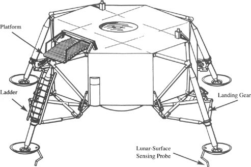
The lunar module’s descent stage. (Courtesy Northrop/Grumman Corporation) (
Illustration credit 5.4
)
To establish the most basic geometry of the landing gear, namely, its tread (distance between opposite footpads) and its height (distance from the surface to the bottom of the descent stage), required a complex systems engineering study. From analyses and ground-based flight simulations, the Flight Controls Group determined the expected tolerances in touchdown velocity that could be expected. These tolerances were expressed statistically as the probability of not exceeding a given value, based upon hundreds of computer and manned simulation runs. After examining the statistics and consulting with NASA and the astronauts, we recommended and NASA accepted the following touchdown parameter limits to be used in LM design: (1) ten feet per second vertical velocity with zero horizontal velocity, (2) seven feet per second vertical velocity with four feet per second horizontal velocity, and (3) vehicle attitude within six degrees of local horizontal.
These touchdown parameters had to be applied to a set of design assumptions about the lunar surface. Here I relied upon NASA, whose experts had been studying what was known about potential landing sites. We arrived at the following lunar surface characteristics for design: (1) six-degree maximum general slope, (2) twenty-four-inch depressions and protuberances, and (3) surface friction coefficients between ice and rock.
Our Structural Analysis Section under Dick Hilderman, working closely with the Structural and Mechanical Design Sections, worked out a multi-variable matrix of analyses, starting with different assumed LM spacecraft and
landing-gear geometries and covering the full range of touchdown velocities and lunar surface conditions. Many thousands of computer runs were required in this iterative, trial-and-error process to find the bounds of acceptable vehicle and landing-gear geometry for landing. The analyses extended over many months and were still being updated and refined well into 1966. By August 1963, though, we were able to freeze the geometry for the M-1 mockup, and the subsequent dimensional changes to the landing gear did not exceed a few inches.
As we explored the analyses, certain combinations of variables came to be recognized as critical, and we could save time by testing new geometries against these critical conditions first. For example, the critical condition for LM tipover resulted from landing at maximum horizontal velocity (four feet per second) downhill on a six-degree surface slope with the LM attitude pitched downhill at six degrees. The initial surface contacted was ice, but at maximum downhill sliding velocity the footpads hit a solid rock curb. The critical condition for energy absorption and ground clearance occurred when the LM touched down at maximum vertical velocity (ten feet per second) with all four footpads landing in twenty-four-inch-deep craters and twenty-four-inch boulders scattered on level ground underneath the descent stage.
Our designers responded good-naturedly to the outrageous combinations of landing design conditions dreamed up by the structural analysts. They took it as a challenge to overcome seemingly impossible landing requirements, if possible with margin to spare. Occasionally I would intervene, deciding that the likelihood of certain combinations appeared so slight that they should be moderated to avoid unduly penalizing the design. The end result, a lunar module twenty-three feet high and thirty-one feet in diameter across the landing gear, represented a cautious approach to the information available at the time. In hindsight, our landing-gear design proved to be extremely conservative. In the actual missions the astronauts skillfully set the LM down “like a crate of eggs” at touchdown velocities of four feet per second or less. The energy absorbing struts were never stroked more than six inches, and the lunar surface conditions were generally more benign than assumed.
The docking mechanism to connect LM to the CM was an interesting engineering problem. It had to be simple, strong, and absolutely reliable because a jam-up would force the astronauts to the more risky option of transferring from one vehicle to another by EVA. Our proposal design used a double-ended cylindrical docking module that could be mated to the docking rings on the CM and either the upper or the forward hatches on the LM. The idea was to provide docking hatch redundancy on the LM side of the connection.
By mid-1963 North American had begun working on an internal probe-and-drogue docking concept, designed to be assembled and disassembled inside the tunnel between the two spacecraft by the crew.
4
The tunnel in each spacecraft was a thirty-two-inch diameter aluminum alloy cylinder about
eighteen inches long located directly above (outside of) the hatches, with machined docking rings on the outer end of each tunnel. The probe mounted in the CM tunnel was driven home into the conical drogue in the LM tunnel and secured by spring-loaded latches. Both the mechanism and the docking maneuver were similar to the air force’s probe-and-drogue aerial refueling and very familiar to military pilots. This was a major argument in favor of the probe-and-drogue approach, and Grumman’s double-ended docking module was discarded.