Secrets of Antigravity Propulsion (18 page)

(7)
φ
g
(r)
∝
– ρE(r) =
∇
•
D
(r) = ε
∇
•
E
(r) = –ε
∇
2
φE(r)
The gradient of this gravity potential field would create a gravitational force on matter that it spanned.
As mentioned earlier, this force would arise because the G-on concentration gradient spatially distorts the etheric wave patterns of the subatomic particles it affects, perturbing them from their ideally spherical symmetric configuration.
Because of their tendency to maintain a state of morphogenic homeostasis, the particles respond to this stress by moving down the gravity potential gradient toward the capacitor’s positive pole.
In accordance with Newton’s second law, the gravitational force acting on a body at point r would be proportional to the negative gradient of the induced gravity potential field at that location multiplied by the body’s inertial mass, which is expressed as
F
g(r) = –Gm
o
∇
φ
g
(r).
Hence using relation 7 to substitute for gravity potential φ
g
(r), the gravitational force on a capacitor is expected to vary in proportion to the third derivative of the electric potential φ
E
(r), or as the derivative of the LaPlacian of the electric potential:
(8)
F
g(r) = k m
o
ε
∇
(
∇
2
φ
E
(r))
As before, the constant
k
in this equation is an experimentally determined electrogravitic proportionality constant that quantifies the virtual-charge-to-virtual-mass coupling relationship.
This thrust on the capacitor dielectric will persist as long as the applied electric field is not canceled out by the opposing electric dipole moment created by the polarization of the dielectric.
By oscillating the electric field to repeatedly create virtual charge, the gravitational thrust may be maintained without complete cancellation.
One thing that becomes apparent from studying relation 8 is that the electrogravitic force should increase as the electric potential field across the capacitor becomes increasingly nonlinear; the more nonlinear the field, the greater the induced gravitational thrust.
Force also increases in accordance with the dielectric’s dielectric constant,
ε, and its mass,
m
o
.
Thus dielectrics with higher K and greater mass will deliver greater thrust.
Brown stressed all of these points in his work.
Furthermore, like the electrogravitic force produced by a real-charge-density gradient, the electrogravitic force arising from a virtual-charge-density gradient will always be directed toward the positive pole.
If the field polarity is reversed, the polarity of the virtual-charge density would also reverse, as would the direction of the gravitic thrust.
Thus, if the smaller electrode in an asymmetrical capacitor was made positive instead of negative, the electrogravitic thrust would be directed once again toward the positive electrode, which in this case would be the smaller of the two electrodes.
Now let us consider a standard symmetrical parallel plate capacitor.
Such a capacitor would develop no virtual-charge-density gradient when charged since its electric field potential would vary linearly across its dielectric.
The only gravity field across its dielectric would be that arising from the charges on its plates.
The negative charges on the negative plate would be producing X-ons and G-ons while the positive charges on the capacitor’s positive plate would be consuming X-ons and G-ons.
Consequently, the X-on and G-on concentrations would be highest at the capacitor’s negative pole and would drop linearly with distance across the dielectric until they reached their lowest value near the capacitor’s positive pole.
These X-on and G-on concentration gradients would be accompanied by a diffusive flux of X-ons and G-ons flowing down the gradient in a uniform manner.
Since any volume in the dielectric would experience the same etheron influx as eflux, the divergence of the X diffusive flux vector would be zero throughout the dielectric, as would be the virtual-charge density.
We may now attempt to calculate the gravity field developed across an asymmetrical AC electrokinetic capacitor having a design similar to that shown in figures 3.2 and 3.6.
We may use electrogravitic relation 7 to determine the virtual-charge profile and gravity potential field that would be generated across the dielectric.
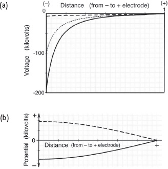
Suppose that a 100-kilovolt DC bias potential were applied across the capacitor plates, with potential varying nonlinearly according to the inverse square of distance as shown by the dotted line in figure 4.5a.
This would plot as the equation V = –1/r
2
.
Compare this with the field potential graph reproduced from Brown’s patent (see figure 3.6).
Note that this field is substantially more nonlinear than the 1/r potential field that would typically exist around a charged sphere.
Let us also suppose that the capacitor’s negative antenna electrode excites a quarter-wave sine wave oscillation across the dielectric with a node at the positive electrode.
If it was a conventional symmetrical capacitor having equal area electrodes, the oscillating potential would vary with distance across the dielectric, as shown in figure 4.5b, in which the solid and dashed curves represent the potential distribution at voltage minimum and voltage maximum.
However, since the capacitor is asymmetrical, with a field that varies with distance in a nonlinear manner, this sine wave amplitude will decrease sharply with distance toward the positive electrode.


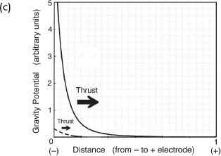
Figure 4.5.
(a) The DC bias potential across the dielectric (dotted line), with
the superimposed resonant oscillation (solid line represents maximum negative;
dashed line represents maximum positive).
(b) Sine wave voltage oscillation
applied across the dielectric in Brown’s electrokinetic apparatus.
(c) The
corresponding gravity potential profile.
(P.
LaViolette, © 2007)
If it were superimposed on the DC bias potential, the overall field would oscillate between the very negative potential profile prevailing when the sine wave oscillation was at its maximum negative voltage (shown as the solid line in figure 4.5a) and the low negative voltage field distribution prevailing when the sine wave oscillation was at its maximum positive voltage (shown as the dashed line in figure 4.5a).
The amplitude of the sinusoidal oscillation at the negative electrode is adjusted to be about 95 percent of the bias voltage.
Using the electrogravitic coupling expression that is presented as relation 7 and including a geometry correction to account for the capacitor’s asymmetrical geometry, the resulting gravity potential distribution is computed to be that shown in figure 4.5c; see text box for details.
The gravity gradient and resulting thrust vary from a minimum to a maximum as the voltage of the sine wave resonance at the negative electrode cycles between positive and negative maxima.
Throughout the AC cycle, the thrust remains always directed toward the positive electrode, but oscillates in magnitude approximately 750 million times per second.
Gravity Potential Distribution in an Asymmetrica
l
Capacitor with a DC Voltage Bias and Applied AC Voltage Oscillation
The gravity potential graphed in figure 4.5c was computed from the following equation:
e
(
r
) =
(
(
∂
)/(
∂
r
)
(
(
− 2
(
∂
)/(
∂
r
)
(
(
1
)/(
r
2
)
(
(
3
)/(
π
)
sin
π
(±0.5 + (
(
r
)/(
12
)
))
)
−
(
1
)/(
r
2
)
)
)
4
π
r
2
)
)
(
1
)/(
4
π
r
2
)
The central term in the brackets represents the electric potential and is given as:
g
(
r
) = − 2
(
(
1
)/(
r
2
)
(
(
3
)/(
π
)
sin
π
(±0.5 + (
(
r
)/(
12
)
))
)
−
(
1
)/(
r
2
)
)
The sine term here represents the sine wave voltage oscillation at its positive and negative maxima.
This is multiplied by 1/
r
2
to model the potential field’s nonlinear variation with distance across the dielectric.
The term –1/
r
2
, which has a similar nonlinear variation with distance
r
, is added to this to represent the DC field bias.
The summed electric potential field has a minus sign, the voltage across the capacitor being negative as referenced from the grounded positive plate.
This quantity is differentiated to derive the electric field gradient,
∇
φ
E
, which by definition is proportional to the negative electric flux density vector, –
D
.
However, since we are dealing with an asymmetrical capacitor with a positive electrode surface area that is larger than the negative electrode surface area, in considering the total electric flux entering or leaving a given spherical shell increment, we must multiply
D
times 4πr
2
, which accounts for the increased surface area toward the positive electrode.
Taking the derivative of this and dividing by 4πr
2
gives the divergence of
D
in that volume increment.
Then, multiplying by –1, we get the virtual-charge density in that increment,
ρ
E
(r).
The negative of this, in turn, gives the gravity potential, φ
g
(r), which is the quantity plotted in figure 4.5c.
Note that if the voltage potential across the dielectric instead was to vary only as 1/r, as do fields radiating from a charged sphere, then in that case the divergence would be zero, since the flux per unit surface area would not change with distance.
Hence, such a field, although nonlinear, would not produce a virtual-charge-density gradient.
