Carrier (1999) (26 page)
Authors: Tom - Nf Clancy

Just aft of Pri-Fly is arguably the most popular spot on board, “Vultures Row”—an open-air balcony overlooking the flight deck (and a good place to take in some sun). There anyone can safely watch the comings and goings below (bring your camera and earplugs!). It also offers a wide view of the whole ship, especially the defensive and sensor system.
From there you can see the sponson mounts for the eight-round Mk. 29 Sea Sparrow SAM launchers. The
Nimitz-
class carriers each have three of these systems, one forward on the starboard side, with the other two aft (port and starboard). The RIM-7M Sea Sparrow is a short-range SAM, designed to support the Mk. 15 CIWS mounts in defending the ship against any “leaker” aircraft or missile that makes it past the screen of Aegis missile cruisers and destroyers supporting the carrier group. Based upon the venerable AIM-7 Sparrow air-to-air missile (AAM), Sea Sparrow was originally developed to provide small ships like frigates and destroyers with a short-range point-defense SAM at a reasonable cost. NATO adopted the system as the standard short-range SAM system for small escorts. Like its AAM cousin, Sea Sparrow utilizes a guidance system known as “semi-active” homing. This means that a Mk. 91 fire-control radar (each
Nimitz-
class carrier has three of these) “illuminates” an incoming missile or aircraft, much as a flashlight is aimed at an object in a dark room. The seeker head of the missile “sees” the targets reflected radar energy from the Mk. 91 radar. The guidance system of the missile then automatically provides it tracking to the target.
40
Nimitz-
class carriers each have three of these systems, one forward on the starboard side, with the other two aft (port and starboard). The RIM-7M Sea Sparrow is a short-range SAM, designed to support the Mk. 15 CIWS mounts in defending the ship against any “leaker” aircraft or missile that makes it past the screen of Aegis missile cruisers and destroyers supporting the carrier group. Based upon the venerable AIM-7 Sparrow air-to-air missile (AAM), Sea Sparrow was originally developed to provide small ships like frigates and destroyers with a short-range point-defense SAM at a reasonable cost. NATO adopted the system as the standard short-range SAM system for small escorts. Like its AAM cousin, Sea Sparrow utilizes a guidance system known as “semi-active” homing. This means that a Mk. 91 fire-control radar (each
Nimitz-
class carrier has three of these) “illuminates” an incoming missile or aircraft, much as a flashlight is aimed at an object in a dark room. The seeker head of the missile “sees” the targets reflected radar energy from the Mk. 91 radar. The guidance system of the missile then automatically provides it tracking to the target.
40
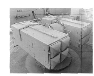
An eight-round Mk. 29 RIM-7M Sea Sparrow launcher aboard the USS George
Washington
(CVN-73).
Washington
(CVN-73).
JOHN D. GRASHAM
Sea Sparrow is an excellent point-defense system that gives the ship good protection out to a range of up to 10 nm/18.5 km. Back in the 1980’s, it was enhanced through the addition of a Mk. 23 Target Acquisition System (TAS) radar. This fast-rotating system can detect low-flying and high-angle targets, and then pass them along automatically to the Sea Sparrow system for engagement. The system’s only drawback is that once the eight ready rounds have been fired from the Mk. 29, the launcher must be manually reloaded. Sea Sparrow is being improved through the development of the Enhanced Sea Sparrow Missile (ESSM) System, which marries the basic seeker system with a new airframe. This will give ESSM more range and performance than RIM- 7M, as well as the ability to be fired from both Mk. 29’s and the Mk. 41 vertical launch system (VLS) launchers found on newer warships.
Unlike surface ships, flattops do not have many convenient spots for placing antennas for radios and sensors. This has to do partly with maintaining appropriate separation between emitting antennas, and partly with the need to avoid clutter on the flight deck during flight operations. For this reason, the island structures of American carriers have always been antenna farms. You’ll also find a number of UHF/VHF radio antennas on the edge of the flight deck, placed on special mounts that rotate horizontally during flight operations. On
Nimitz-
class carriers there is additionally a large antenna mast just aft of the island, to hold those radar and communications antennas that need to be as high as possible. These masts and mounts hold a variety of sensors including:
Nimitz-
class carriers there is additionally a large antenna mast just aft of the island, to hold those radar and communications antennas that need to be as high as possible. These masts and mounts hold a variety of sensors including:
•
SPS-48E
—A 3-D air-search radar that provides air traffic control and battle management functions. This high-resolution radar has a reported range out to approximately 60 nm/110 km.
SPS-48E
—A 3-D air-search radar that provides air traffic control and battle management functions. This high-resolution radar has a reported range out to approximately 60 nm/110 km.
•
SPS-49(V)5
—This is the best current Naval 2-D air-search radar. Extremely reliable, with a detection range of up to several hundred miles/ kilometers, SPS-49’s are found on most major combatants in the U.S. Navy, as well as many foreign vessels.
SPS-49(V)5
—This is the best current Naval 2-D air-search radar. Extremely reliable, with a detection range of up to several hundred miles/ kilometers, SPS-49’s are found on most major combatants in the U.S. Navy, as well as many foreign vessels.
•
SPS-64(V)9
—This is primarily a surface-search/navigation radar for keeping formation and operating close to shore. It is a development of the classic Litton LN-66 navigation radar.
SPS-64(V)9
—This is primarily a surface-search/navigation radar for keeping formation and operating close to shore. It is a development of the classic Litton LN-66 navigation radar.
•
SPS-67
—The SPS-67 is a general-purpose surface-search radar, designed to provide precise targeting data against surface targets.
SPS-67
—The SPS-67 is a general-purpose surface-search radar, designed to provide precise targeting data against surface targets.
•
Mk. 23 Target Acquisition System (TAS)
—This is a small, fast-rotating radar for detecting sea-skimming or high-angle missile attacks. It feeds data directly into the SYS-2 (V)3 weapons-control system, which can automatically activate the RIM-7/Mk. 29 Sea Sparrow SAM systems.
Mk. 23 Target Acquisition System (TAS)
—This is a small, fast-rotating radar for detecting sea-skimming or high-angle missile attacks. It feeds data directly into the SYS-2 (V)3 weapons-control system, which can automatically activate the RIM-7/Mk. 29 Sea Sparrow SAM systems.
•
Mk. 91 Fire Control System (FCS)—
The three Mk. 91 FCSs provide guidance for the RIM-7M Sea Sparrow SAM launched by the three Mk. 29 launchers.
Mk. 91 Fire Control System (FCS)—
The three Mk. 91 FCSs provide guidance for the RIM-7M Sea Sparrow SAM launched by the three Mk. 29 launchers.
•
SLQ-32 (V)4
—The SLQ-32 is a family of electronic-warfare systems, which can be tailored to the protection requirements of a particular ship. The (V)4 version has a wide-band radar-warning receiver, a wide-band radar jammer, and a bank of Mk. 137 Super Rapid Blooming Chaff (SRBOC) launchers. These six-barreled mortars throw up a cloud of chaff (metal-coated Mylar strips) and infrared decoys to blind or confuse an incoming missile at the last moment prior to an attack.
•
WRL-1H
—The WRL-1H is a general-purpose wide-band radio/radar-warning /intercept receiver, designed to provide a basic intercept capability for everything from radio traffic to bearings on radar sets.
WRL-1H
—The WRL-1H is a general-purpose wide-band radio/radar-warning /intercept receiver, designed to provide a basic intercept capability for everything from radio traffic to bearings on radar sets.
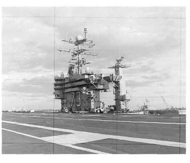
The array of antennas on the island structure of the USS
George Washington
(CVN-73). This is representative of the configuration on late-production
Nimitz-
class (CVN-68) carriers.
George Washington
(CVN-73). This is representative of the configuration on late-production
Nimitz-
class (CVN-68) carriers.
JOHN D. GRESHAM
These systems give the carrier’s commanding officer and battle group staff good situational awareness of the battle space surrounding their ship and the ARG. Along with the supporting sensor systems, the island also provides mounts for many of the ship’s communications systems. While many of these are classified, they cover the full range of the electromagnetic spectrum and functions. The most interesting of these are the domed antennas for the satellite communications systems, which provide much of the high-reliability secure communications for the battle group.
Since they were originally designed primarily to transmit encoded text messages, even these systems have limits. Today, carriers need a lot more than just a relatively slow, secure means of receiving words. This problem surfaced with particular impact during Desert Storm, when none of the U.S. Navy carriers had the ability to receive the daily Air Tasking Order (ATO) from CENTCOM’s air command in Riyadh. Every other air unit in the theater, including those of our allies, could get the ATO (which ran to hundreds of pages of densely formatted text), even if only by high-speed FAX machines over secure phone lines. But the Navy, having always planned on fighting on their own in the open ocean, was ill prepared for the communications required for joint operations with other services. As a result, the Navy did not receive its daily delivery of the ATO by high-tech satellite or data link, but by hand-delivered paper copies flown in by an S-3 Viking. As might be imagined, this was quite an embarrassment for the Navy, and as a result it began to put together systems to relieve this lack of joint connectivity.
The first try at a solution to the problem was known as the “Challenge Athena” experiment. Challenge Athena I—initially an experimental system on board the USS
George Washington
(CVN-73)—is a two-way, low-speed (around 768 kilobytes per second—kps) satellite link based upon commercial antenna technology. Originally developed for use in delivering intelligence photos and conducting video teleconferences, it has grown into a much broader communications system, and in the process has become incredibly popular with everyone in the fleet. Along with the obvious benefits to top planners and commanders, Challenge Athena provides the crew not only with two-way E-mail contact home, but also with direct live access to commercial television channels like CNN and ESPN. A new high-speed version of the system, Challenge Athena III, is about to be installed throughout the carrier force, as well as on fleet flagships, big-deck amphibious ships, and perhaps even major combatants like the Aegis cruisers and destroyers. A comparable system is being developed for use by submarines, to support Tomahawk cruise-missile targeting, special operations, and unmanned aerial vehicle (UAV) missions. The domed Challenge Athena antennas are located on the flight deck level, outboard of the island and the crotch.
Now it is time to go below. After a drop down a stack of six ladders from the bridge, we find ourselves on the 03 or “Gallery” level, directly under the flight deck. Heading inboard, we find two central passageways running the length of the full ship. Almost a quarter-mile long, these passageways seem to go on forever, with only an occasional cross-passageway to break the monotony of “knee knockers” and watertight hatches. Most of what we see here are doors, lots of them, behind some of which are the real “brains” of the ship—the various command, air wing, and squadron spaces. In addition, most of the air wing officers and flag staff personnel live here. If you turn left and head aft down the main starboard passageway, you pass compartments filled with the hydraulic cylinders for the arresting-gear system. These are gigantic, filling the space between the two main corridors. The compartments here are also even more spotlessly clean than the rest of the ship, since one of the first signs of trouble in a hydraulic system is telltale leaks of fluid.
Farther aft are many of the squadron ready rooms. These large spaces are the headquarters for the various flying squadrons and detachments attached to the carrier’s embarked air wing. The ready room is the inner sanctum of a flying squadron, a combination of clubhouse, rest area, and meeting/ briefing/planning center. Since the rules of naval aviation allow a freedom of speech and expression that would not be tolerated in other areas aboard ship, ready rooms are extremely private places (where life as a naval aviator is seen at its most raw and splendid). This means that they are for aviators and
only
aviators, and permission is required before
anyone
else is allowed inside.
only
aviators, and permission is required before
anyone
else is allowed inside.
Ready rooms are wondrous places, filled with historic photos, trophies, and plaques from the unit’s past. At the front of the ready room is the desk for the squadron duty officer and a large white board for briefings and discussions. There also are rows of the most comfortable chairs you will ever sit in. Based on a design that predates the Second World War, they are soft but firm, with thick leather covers embossed with the squadron’s colors and logo. They can also recline for a short nap between sorties, and have fold-down writing tables for scribbling notes.
At the rear of the room is a small enclosed area where the terminal for the Tactical Aircrew Mission Planning System (TAMPS) is located. TAMPS is an automated system that allows air crews to perform route and mission planning. Since it can take into account effects like terrain masking and enemy air defense weapons envelopes, TAMPS is a major improvement over the old system of paper maps, photos, and air crew intuition. After each squadron does their planning over the networked TAMPS system, the staff of the air wing can review an entire strike/mission plan before the mission is flown.
After leaving the ready room, we’ll head forward. After we’ve passed through about a third of the ship, the tile changes from normal Navy gray to a bright blue, meaning that we have reached what the crew calls “blue tile country.” This is the central command and control complex for both the ship and the carrier battle group. The deck in “blue tile country” is subdivided into a series of spaces, each dedicated to a different set of warfare tasks. These include:
•
Combat Information Center (CIC)
—This is the battle nerve center of the ship, with displays for all of the ship’s sensors, as well as information acquired from data links and national sources (the DoD term for reconnaissance satellites, aircraft, and other systems). The CIC is specifically designed to present all the available data on the combat situation to the officers making the decisions about how to “fight” the ship. Filled with consoles, terminals, and big-screen displays, this space has separate zones for antisub, antiair, and antisurface warfare, communications, damage control, and other functions. Back in World War II a captain normally fought his ship from the bridge, but today’s Arleigh Burke or Phillip Vian will normally be found at a glowing console within a dimly lit CIC. Aircraft carriers’ CICs are somewhat different from those of other ships. On a carrier, not all of the terminals and personnel are in a single room, as they are on an Aegis cruiser or destroyer. This better hardens the ship against attack, and avoids a huge and overmanned space, which could be destroyed by a single hit. Thus, the various warfare specialties—antiair (AAW), antisubmarine (ASW), antisurface (ASUW), etc.—have their own small control centers, which forward their data into the main CIC.
•
Carrier Air Traffic Control Center (CATCC)—
The CATCC is a control center for handling airspace and traffic control around the battle group. This one is different from a local FAA control center, in that it moves with the ship and has the ability to data-link information from offboard sensor systems like Aegis ships and AEW aircraft (E-2Cs, E-3’s, etc.).
•
Tactical Flag Command Center
—The TFCC is essentially a duplicate in miniature of the CIC. The difference is that the TFCC is specially configured to maximize access to data that flag officers (i.e., admirals/ battle group commanders) need. To support this requirement, the TFCC was developed with the same kinds of large-screen displays and workstations that you would find aboard the Aegis ships that screen the carrier. (The TFCC used to be called “Flag Plot,” but that space now resides up on the island.)
•
Joint Intelligence Center (JIC)
—The Joint Intelligence Center is a clearinghouse for information required by the ship, the battle group, and embarked air units. Analysts in the JIC can draw from vast databases of National Imagery and Mapping Agency (NIMA) maps, satellite photography, and anything else the intelligence community provides. The JIC staff is a “rainbow” organization from every unit in the battle group, as well as from other services and intelligence organizations. Even better, they can
probably
tell you what it all means.
•
Ships Signals Exploitation Space (SSES)
—This small sealed space is for the
really
secret stuff: “exploitation” of enemy radio signals and electronic emissions. Equipped with data links to national and theater-level intelligence systems, the SSES can provide battle group leaders with up-to-date information on enemy intentions and activities. Only specially cleared intelligence and communications technicians are allowed inside.
Other books
Risky: Torn Between Two Lovers by Jo Davis
Justifying Jack (The Wounded Warriors Book 2) by Beaudelaire, Simone, Northup, J.M.
Mrs R (Mrs R & Mr V #1) by Jessie Courts
Grunts by John C. McManus
One Dog at a Time by Farthing, Pen
How to Murder the Man of Your Dreams by Dorothy Cannell
Dragon's Egg by Robert L. Forward
Blacker than Black by Rhi Etzweiler
She Survived by M. William Phelps
Disclosures - SF4 by Meagher, Susan X