Make: Electronics (63 page)
Authors: Charles Platt

Each of the LEDs is grounded through a separate 4K7 load resistor. Unfortunately, this means that when they are displaying the pattern for a 6, all of them are running in parallel from the output of the NOR gate, which overloads it. As long as you don’t leave the display in this mode for very long periods, it shouldn’t cause a problem. You could compensate by increasing the load resistors, or by running pairs of the LEDs through one resistor, but this will make them so dim that they’ll be difficult to see, as they’re so close to their lower limit for current already.
Notice how I have added four signal diodes, D1 through D4. When Output C goes high, it has to illuminate all four corner LEDs, and so its power goes into the brown wire as well as the gray wire. But we must never allow one output to feed back into another, so D4 is needed to protect Output B when Output C is high.
Because there is now a connection between B and C, we need D2 to protect Output C when Output B is high. And because Output B must only feed two of the corner LEDs, we also need D3 to stop it from illuminating the other two. And, we have to protect the output from the NOR gate when either Output C or Output B is high. This requires D1.
Figure 4-109 shows everything that I’ve described so far assembled in breadboard format, while Figure 4-110 shows the test version that I built. Note that the unused logical inputs on the 74LS27 chip are shorted together and connected to the
positive
side of the power supply. Here’s the rule:
- When using CMOS chips (such as the HC series), connect unused logical inputs to the negative side of the power supply.
- When using TTL chips (such as the LS series), connect unused logical inputs to the positive side of the power supply.
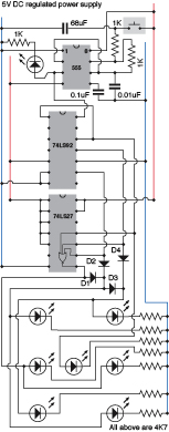
Figure 4-109.
With some extra components, the schematics from Figures 4-102 and 4-107 can be combined to make the working dice simulation.
I assume that you have had enough fun watching the LEDs count slowly, so I’ve changed the capacitor and resistor values for the 555 to increase its speed from approximately 1 pulse per second to about 50,000 pulses per second. The counter could run much faster than this, but I just want it to cycle fast enough so that when the user presses and releases a button, the count will stop at an unforeseeable number.
The button starts and stops the 555 timer by applying and releasing power to the timing circuit only. This is the equivalent of shaking and then throwing the die.
While the counter is running fast, the LEDs are flashing so fast that all of them will seem to be on at once. At the same time, the circuit charges a new 68 µF capacitor, which I have added between the pushbutton and ground. When you release the button, this capacitor discharges itself through the 1K timing resistor. As the charge dissipates, the timing capacitor will take longer and longer to charge, and discharge, and the frequency of the 555 will gradually diminish. Consequently the LED display will also flash slower, like the reel on a Las Vegas slot machine gradually coming to a stop. This increases the tension as players can see the die display counting to the number that they’re hoping for—and maybe going one step beyond it.
Note that to maximize this effect, the button has to be held down for a full second or more, so that the 68 µF capacitor becomes fully charged before the button is released.
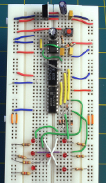
Figure 4-110.
The electronic dice schematic applied to a breadboard, with a pushbutton at the top to start and stop the counter, and 7 LEDs at the bottom to display the output.
So, this circuit now fulfills the original goal. But can it be better? Of course it can.
Enhancements
The main thing I want to improve is the brightness of the LEDs. I could add a transistor to amplify the current to each one, but there’s a simpler alternative: a TTL “open collector” inverter.
I want to use an inverter because in the world of TTL, as I mentioned earlier, we can sink much more power into the output pin of a chip than we can source from it. So, I’m going to turn each LED the other way around and connect their load resistors to the positive side of the power supply. This way, they’ll sink their power into the outputs of the inverter.
And the great advantage of an “open collector” version of the inverter chip is that it is designed to sink much more current than a normal TTL logic chip. It is rated for 40mA per pin. The only disadvantage is that it cannot source any current at all; instead of its output going high, it just behaves like an open switch. But that’s OK for this circuit.
So the next and final schematic, in Figure 4-111, includes the 74LS06 inverter, which has also been added to the breadboarded version shown in Figure 4-112. I suggest that you put aside the little low-current LEDs and substitute some normal-size ones. Using Kingbright “standard” WP15031D 5mm LEDs, I find that each draws almost exactly 20mA with a voltage drop of about 2V with a 120 ohm series resistor. Because each output pin from the 74LS06 inverter powers no more than two LEDs at a time, this is exactly within its specification. I suggest that if you build this circuit, you check the consumption of your particular choice of LEDs and adjust the resistors if necessary.
Remember: to measure the voltage drop across an LED, simply touch the probes of your meter across it while it is illuminated. To measure the current, disconnect one side of the LED and insert the meter, in milliamp mode, between the leg of the LED and the contact that it normally makes in the circuit.
For a really dramatic display, you can get some 1 cm diameter LEDs (Figure 4-113). Check the specification, and you should find that many of these don’t use more power than the usual 5 mm type. But whatever kind you use, don’t forget to turn them around so that their negative sides face toward the inverter, and their positive sides face the resistors, which are connected to the positive side of the power supply.
One last detail: I had to add two 10K resistors to this version of the circuit. Can you see why? Diodes D1 through D4 are designed to transmit positive voltage through to the inverter when appropriate, but they prevent the inputs of the inverter from “seeing” the negative side of the power supply when the counter outputs are low. These inverter inputs require pull-down resistors to prevent them from “floating” and producing erroneous results.
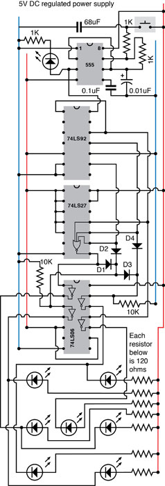
Figure 4-111.
If open-collector inverters are added to the dice schematic, it can drive full-size LEDs with up to 40mA, as long as the LEDs are turned around to sink current into the TTL output stage instead of trying to source current from it.
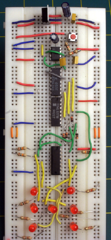
Figure 4-112.
The completed circuit using an open-collector inverter to drive full-size LEDs.
The final enhancements are up to you. Most obviously, you can add a second die, as many games require two dice. The 74LS27 chip still has a couple of spare NOR gates in it, one of which you can make use of, but you will need an additional 555 timer, running at a significantly different speed to ensure randomness, and it will have to drive a second counter.
After you get your dice up and running, you may want to test them for randomness. Because the pulses from a 555 timer are of equal length, every number has an equal chance of coming up; but the longer you hold down the Start button, the better your odds are of interrupting the counting process at a truly random moment. Anyone using your electronic dice should be told that “shaking” them for a full second is mandatory.
Of course, I could have simulated dice more easily by writing a few lines of software to generate random numbers on a screen, but even a fancy screen image cannot have the same appeal as a well-made piece of hardware. Figure 4-113 shows white 1 cm LEDs mounted in a sanded polycarbonate enclosure for dramatic effect.
Most of all, I derived satisfaction from using simple, dedicated chips that demonstrate the binary arithmetic that is fundamental in every computer.
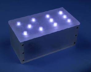
Figure 4-113.
The open-collector inverter chip in the dice circuit is sufficiently powerful to drive 1-cm white LEDs that draw about 20mA each, using a potential of 2V. In this finished version, the LEDs were embedded in cavities drilled from the underside of half-inch polycarbonate, which has been treated with an orbital sander to create a translucent finish.
Experiment 24: Intrusion Alarm Completed
Now let me suggest how you can apply the knowledge from this chapter of the book to upgrade the burglar alarm project that was last modified in
Experiment 15
. You’ll probably need to check Chapters 2 and 3 to refamiliarize yourself with some features of the alarm.
Upgrade 1: Delayed Activation
The biggest flaw in the alarm was that as soon as it was activated, it would immediately respond to any signal from the door and window sensors. It needed a feature to delay activation to give you a chance to exit from the building before the alarm armed itself. A 555 timer can provide this functionality, probably in conjunction with a relay. The power to the alarm should pass through the contacts of the relay, which are normally closed. When you press a button on the timer, it sends a positive pulse to the relay lasting for around 30 seconds, holding the relay open for that period. You could mount the timer in its own little box with a button on it, which you press when you’re ready to leave the building. The 12-volt power supply to the burglar alarm passes through the box containing the delay circuit. For 30 seconds, the 555 interrupts power to the alarm, and then restores it, ready for action.