Make: Electronics (62 page)
Authors: Charles Platt

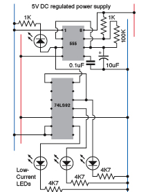
Figure 4-102.
This simple circuit uses a 555 timer running slowly to control the 74LS92 binary counter and display the succession of high states from its outputs.
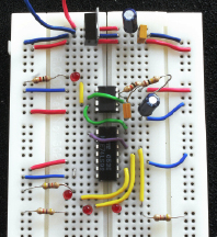
Figure 4-103.
The breadboard version of the schematic in Figure 4-102 to display the outputs from a 74LS92 counter.
Now we come to the first new and difficult fact about the 74LSxx generation of TTL chips that makes them less desirable, for our purposes, than the 74HCxx generation of CMOS chips that I have recommended in previous projects. The modern and civilized HC chips will source 4mA or sink 4mA at each logical output, but the older LS generation is fussier. It will sink around 8mA into each output pin from a positive source, but when its output is high, it hardly gives you anything at all. This is a very basic principle:
- Outputs from TTL logic chips are designed to sink current.
- They are not designed to source significant current.
In fact, the 74LS92 is rated to deliver less than half a milliamp. This is quite acceptable when you’re just connecting it with another logic chip, but if you want to drive an external device, it doesn’t provide much to work with.
The proper solution is to say to the chip, “All right, we’ll do it your way,” and set things up with a positive source that flows through a load resistor to the LED that you want to use, and from there into the output from the chip. This is the “better” option shown in Figure 4-104.
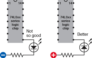
Figure 4-104.
Most TTL chips, including those in the LS generation, are unable to source much current from their logical output pins (left) and should usually be wired to sink current from a positive source (right).
The only problem is that now the LED lights up when the counter’s output is low. But the counter is designed to display its output in high pulses. So your LED is now off when it should be on, and on when it should be off.
You can fix this by passing the signal through an inverter, but already I’m getting impatient with this inconvenience. My way around the problem, at least for demo purposes, is to use the “Not so good” option in Figure 4-104 and make it work by connecting a very-low-current LED with a large 4K7 load resistor. This will enable us to “see” the output from the counter without asking it to give more than its rated limit, and if you want to create a more visibly powerful display for a finished version of the dice circuit, I’ll deal with that later. According to my meter, the 4K7 resistor holds the current between 0.3mA and 0.4mA, which is the counter’s rated maximum.
Set up your initial version of the circuit as shown in Figures 4-102 and 4-103. Be careful when you wire the positive and negative power supply to the counter chip, with its nonstandard pin assignments.
The 555 will run in astable mode, at about 1 pulse per second. This becomes the clock signal for the counter. The first three binary outputs from the counter then drive the three LEDs.
The counter advances when the input signal goes from
high
to
low
. So when the LED beside the 555 timer goes out, that’s when the counter advances.
If you stare at the pattern generated by the outputs for long enough, you may be able to see the logic to it, bearing in mind that its zero state is when they are all off, and it counts up through five more steps before it repeats. The diagram in Figure 4-105 shows this sequence. If you want to know why the pattern works this way, check the following section, “Theory: Binary arithmetic.”
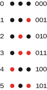
Figure 4-105.
The three output pins of the 74LS92 counter have high states shown by the red circles as the counter steps from 000 to 101 in binary notation.
Theory
Binary arithmetic
The rule for binary counting is just a variation of the rule that we normally use for everyday counting, probably without thinking much about it. In a 10-based system, we count from 0 to 9, then carry 1 over to the next position on the left, and go from 0 to 9 again in the right-most position. We repeat this procedure until we get to 99, then carry a 1 over to a new position to make 100, and continue counting.
In binary we do the same thing, except that we restrict ourselves to digits 0 and 1 only. So begin with 0 in the rightmost position, and count up to 1. As 1 is our limit, to continue counting we carry 1 over to the next place on the left, and start again from 0 in the right-most position. Count up to 1, then add 1 to the next place on the left—but, it already has a 1 in it, so it can’t count any higher. So, carry 1 from there one space further, to the next place beside that—and so on.
If a glowing LED represents a 1, and a dark LED represents a 0, the diagram in Figure 4-105 shows how the 74LS92 counts up from 0 to (decimal) 5 or (binary) 101 in its inimitable fashion. I’ve also included a diagram in Figure 4-106 showing how a counter with four binary outputs would display decimal numbers from 0 through 15, again using the LEDs to represent 1s and 0s.
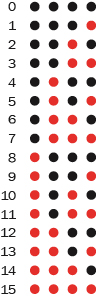
Figure 4-106.
A hexadecimal (16-based) binary counter would generate this succession of high states from its four output pins as it counts from 0 through 15 in decimal notation.
Here’s a question for you: how many LEDs would you need to represent the decimal number 1024 in binary? And how many for 1023?
Obviously binary code is ideally suited to a machine full of logic components that either have a high or a low state. So it is that all digital computers use binary arithmetic (which they convert to decimal, just to please us).
Getting back to our project: I want to take the three binary outputs and make them create patterns like the spots on a die. How can I do this? Quite easily, as it turns out.
I’m assuming that I’ll use seven LEDs to simulate the patterns of spots on a die. These patterns can be broken down into groups, which I have assigned to the three outputs from the counter in Figure 4-108. The first output (farthest to the right) can drive an LED representing the dot at the center of the die face. The second (middle) output can drive two more diagonal LEDs. The third output must switch on all four corner LEDs.
This will work for patterns 1 through 5, but won’t display the die pattern for a 6. Suppose I tap into all three outputs from the counter with a three-input NOR gate. It has an output that goes high only when all three of its inputs are low, so it will only give a high output when the counter is beginning with all-low outputs. I can take advantage of this to make a 6 pattern.
Note that it’s bad practice to mix the LS generation of TTL chips with the HC generation of CMOS chips, as their input and output ranges are different; so, the NOR chip has to be a 74LS27, not a 74HC27.
We’re ready now for a simple schematic. In Figure 4-107 I’ve colored some of the wires just to make it easier for you to distinguish them. The colors have no other significance.
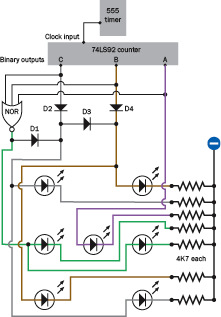
Figure 4-107.
A simplified schematic shows how outputs from the 74LS92 counter can be combined, with signal diodes and a single three-input NOR gate, to generate the spot patterns on a die. The wire colors have no special meaning and are used just to distinguish them from each other.
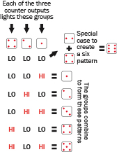
Figure 4-108.
Binary outputs from the 74LS92 counter can be used to power LEDs arrayed in groups to simulate the pattern of spots on a die.