The Elements of Computing Systems: Building a Modern Computer from First Principles (5 page)
Read The Elements of Computing Systems: Building a Modern Computer from First Principles Online
Authors: Noam Nisan,Shimon Schocken

BOOK: The Elements of Computing Systems: Building a Modern Computer from First Principles
12.71Mb size Format: txt, pdf, ePub

Figure 1.2
All the Boolean functions of two variables.
All the Boolean functions of two variables.
The Nand function (as well as the Nor function) has an interesting theoretical property: Each one of the operations And, Or, and Not can be constructed from it, and it alone (e.g.,
x
Or
y
= (
x
Nand x) Nand (
y
Nand y). And since every Boolean function can be constructed from And, Or, and Not operations using the canonical representation method, it follows that every Boolean function can be constructed from Nand operations alone. This result has far-reaching practical implications: Once we have in our disposal a physical device that implements Nand, we can use many copies of this device (wired in a certain way) to implement in hardware any Boolean function.
1.1.2 Gate Logicx
Or
y
= (
x
Nand x) Nand (
y
Nand y). And since every Boolean function can be constructed from And, Or, and Not operations using the canonical representation method, it follows that every Boolean function can be constructed from Nand operations alone. This result has far-reaching practical implications: Once we have in our disposal a physical device that implements Nand, we can use many copies of this device (wired in a certain way) to implement in hardware any Boolean function.
A
gate
is a physical device that implements a Boolean function. If a Boolean function f operates on n variables and returns
m
binary results (in all our examples so far, m was 1), the gate that implements f will have n input pins and m output pins. When we put some values v
1
...v
n
in the gate’s input pins, the gate’s “logic”—its internal structure—should compute and output
f
(
υ
1
...
υ
n
). And just like complex Boolean functions can be expressed in terms of simpler functions, complex gates are composed from more elementary gates. The simplest gates of all are made from tiny switching devices, called transistors, wired in a certain topology designed to effect the overall gate functionality.
Although most digital computers today use electricity to represent and transmit binary data from one gate to another, any alternative technology permitting switching and conducting capabilities can be employed. Indeed, during the last fifty years, researchers have built many hardware implementations of Boolean functions, including magnetic, optical, biological, hydraulic, and pneumatic mechanisms. Today, most gates are implemented as transistors etched in silicon, packaged as chips. In this book we use the words chip and gate interchangeably, tending to use the term gates for simple chips.
The availability of alternative switching technology options, on the one hand, and the observation that Boolean algebra can be used to abstract the behavior of any such technology, on the other, is extremely important. Basically, it implies that computer scientists don’t have to worry about physical things like electricity, circuits, switches, relays, and power supply. Instead, computer scientists can be content with the abstract notions of Boolean algebra and gate logic, trusting that someone else (the physicists and electrical engineers—bless their souls) will figure out how to actually realize them in hardware. Hence, a primitive gate (see figure 1.3) can be viewed as a black box device that implements an elementary logical operation in one way or another—we don’t care how. A hardware designer starts from such primitive gates and designs more complicated functionality by interconnecting them, leading to the construction of composite gates.
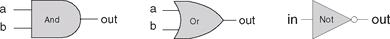
Figure 1.3
Standard symbolic notation of some elementary logic gates.
Standard symbolic notation of some elementary logic gates.

Figure 1.4
Composite implementation of a three-way And gate. The rectangle on the right defines the conceptual boundaries of the gate interface.
Composite implementation of a three-way And gate. The rectangle on the right defines the conceptual boundaries of the gate interface.
Primitive and Composite Gates
Since all logic gates have the same input and output semantics (0’s and 1’s), they can be chained together, creating composite gates of arbitrary complexity. For example, suppose we are asked to implement the 3-way Boolean function And(
a, b, c
). Using Boolean algebra, we can begin by observing that
a·b·c
= (
a
·
b
)·
c
, or, using prefix notation, And(
a
, b, c) = And(And(
a, b
),
c
). Next, we can use this result to construct the composite gate depicted in figure 1.4.
The construction described in figure 1.4 is a simple example of gate logic, also called logic design. Simply put, logic design is the art of interconnecting gates in order to implement more complex functionality, leading to the notion of composite gates. Since composite gates are themselves realizations of (possibly complex) Boolean functions, their “outside appearance” (e.g., left side of figure 1.4) looks just like that of primitive gates. At the same time, their internal structure can be rather complex.
We see that any given logic gate can be viewed from two different perspectives: external and internal. The right-hand side of figure 1.4 gives the gate’s internal architecture, or implementation, whereas the left side shows only the gate interface, namely, the input and output pins that it exposes to the outside world. The former is relevant only to the gate designer, whereas the latter is the right level of detail for other designers who wish to use the gate as an abstract off-the-shelf component, without paying attention to its internal structure.
Let us consider another logic design example—that of a Xor gate. As discussed before, Xor(
a
, b) is 1 exactly when either a is 1 and
b
is 0, or when a is 0 and
b
is 1. Said otherwise, Xor(
a, b
) = Or(And(
a
, Not(
b
)), And(Not(
a
),
b
)). This definition leads to the logic design shown in figure 1.5.
a
, b) is 1 exactly when either a is 1 and
b
is 0, or when a is 0 and
b
is 1. Said otherwise, Xor(
a, b
) = Or(And(
a
, Not(
b
)), And(Not(
a
),
b
)). This definition leads to the logic design shown in figure 1.5.
Note that the gate interface is unique: There is only one way to describe it, and this is normally done using a truth table, a Boolean expression, or some verbal specifica-tion. This interface, however, can be realized using many different implementations, some of which will be better than others in terms of cost, speed, and simplicity. For example, the Xor function can be implemented using four, rather than five, And, Or, and Not gates. Thus, from a functional standpoint, the fundamental requirement of logic design is that
the gate implementation will realize its stated interface, in one way or another
. From an efficiency standpoint, the general rule is to try to do more with less, that is, use as few gates as possible.
the gate implementation will realize its stated interface, in one way or another
. From an efficiency standpoint, the general rule is to try to do more with less, that is, use as few gates as possible.

Figure 1.5
Xor gate, along with a possible implementation.
Xor gate, along with a possible implementation.
To sum up, the art of logic design can be described as follows: Given a gate specification (interface), find an efficient way to implement it using other gates that were already implemented. This, in a nutshell, is what we will do in the rest of this chapter.
1.1.3 Actual Hardware ConstructionHaving described the logic of composing complex gates from simpler ones, we are now in a position to discuss how gates are actually built. Let us start with an intentionally naïve example.
Suppose we open a chip fabrication shop in our home garage. Our first contract is to build a hundred Xor gates. Using the order’s downpayment, we purchase a soldering gun, a roll of copper wire, and three bins labeled “And gates,” “Or gates,” and “Not gates,” each containing many identical copies of these elementary logic gates. Each of these gates is sealed in a plastic casing that exposes some input and output pins, as well as a power supply plug. To get started, we pin figure 1.5 to our garage wall and proceed to realize it using our hardware. First, we take two And gates, two Not gates, and one Or gate, and mount them on a board according to the figure’s layout. Next, we connect the chips to one another by running copper wires among them and by soldering the wire ends to the respective input/output pins. Now, if we follow the gate diagram carefully, we will end up having three exposed wire ends. We then solder a pin to each one of these wire ends, seal the entire device (except for the three pins) in a plastic casing, and label it “Xor.” We can repeat this assembly process many times over. At the end of the day, we can store all the chips that we’ve built in a new bin and label it “Xor gates.” If we (or other people) are asked to construct some other chips in the future, we’ll be able to use these Xor gates as elementary building blocks, just as we used the And, Or, and Not gates before.
As the reader has probably sensed, the garage approach to chip production leaves much to be desired. For starters, there is no guarantee that the given chip diagram is correct. Although we can prove correctness in simple cases like Xor, we cannot do so in many realistically complex chips. Thus, we must settle for empirical testing: Build the chip, connect it to a power supply, activate and deactivate the input pins in various configurations, and hope that the chip outputs will agree with its specifications. If the chip fails to deliver the desired outputs, we will have to tinker with its physical structure—a rather messy affair. Further, even if we will come up with the right design, replicating the chip assembly process many times over will be a time-consuming and error-prone affair. There must be a better way!
1.1.4 Hardware Description Language(HDL)
Today, hardware designers no longer build anything with their bare hands. Instead, they plan and optimize the chip architecture on a computer workstation, using structured modeling formalisms like Hardware Description Language, or HDL (also known as VHDL, where V stands for
Virtual
). The designer specifies the chip structure by writing an HDL program, which is then subjected to a rigorous battery of tests. These tests are carried out virtually, using computer simulation: A special software tool, called a hardware simulator, takes the HDL program as input and builds an image of the modeled chip in memory. Next, the designer can instruct the simulator to test the virtual chip on various sets of inputs, generating simulated chip outputs. The outputs can then be compared to the desired results, as mandated by the client who ordered the chip built.
Other books
Sacremon (Harmony War Series Book 1) by Michael Chatfield
Mad Cow by J.A. Sutherland
ROMANCE: Military Control: A Dark Military Suspense Romance by Landish, Lucy
La taberna by Émile Zola
Scattered Bones by Maggie Siggins
B009R9RGU2 EBOK by Sweeney, Alison
Cookie's Case by Andy Siegel
Daddy Devastating by Delores Fossen
Azrael by William L. Deandrea
What Blood Leaves Behind (The Poison Rose) by Beaumont, Delany