The Elements of Computing Systems: Building a Modern Computer from First Principles (8 page)
Read The Elements of Computing Systems: Building a Modern Computer from First Principles Online
Authors: Noam Nisan,Shimon Schocken

BOOK: The Elements of Computing Systems: Building a Modern Computer from First Principles
6.31Mb size Format: txt, pdf, ePub
Multi-Way/Multi-Bit Multiplexor
An
m
-way
n
-bit multiplexor selects one of m n-bit input buses and outputs it to a single
n
-bit output bus. The selection is specified by a set of
k
control bits, where
k
= log
2
m
. Figure 1.10 depicts a typical example.
An
m
-way
n
-bit multiplexor selects one of m n-bit input buses and outputs it to a single
n
-bit output bus. The selection is specified by a set of
k
control bits, where
k
= log
2
m
. Figure 1.10 depicts a typical example.
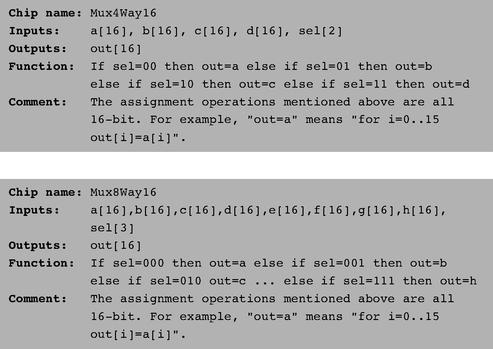
The computer platform that we develop in this book requires two variations of this chip: A 4-way 16-bit multiplexor and an 8-way 16-bit multiplexor:

Figure 1.10
4-way multiplexor. The width of the input and output buses may vary.
4-way multiplexor. The width of the input and output buses may vary.
Multi-Way/Multi-Bit Demultiplexor
An
m
-way
n
-bit demultiplexor (figure 1.11) channels a single
n
-bit input into one of
m
possible
n
-bit outputs. The selection is specified by a set of
k
control bits, where
k
= log
2
m
.
An
m
-way
n
-bit demultiplexor (figure 1.11) channels a single
n
-bit input into one of
m
possible
n
-bit outputs. The selection is specified by a set of
k
control bits, where
k
= log
2
m
.
The specific computer platform that we will build requires two variations of this chip: A 4-way 1-bit demultiplexor and an 8-way 1-bit multiplexor, as follows.

Figure 1.11
4-way demultiplexor.
4-way demultiplexor.

Similar to the role of axioms in mathematics, primitive gates provide a set of elementary building blocks from which everything else can be built. Operationally, primitive gates have an “off-the-shelf” implementation that is supplied externally. Thus, they can be used in the construction of other gates and chips without worrying about their internal design. In the computer architecture that we are now beginning to build, we have chosen to base all the hardware on one primitive gate only: Nand. We now turn to outlining the first stage of this bottom-up hardware construction project, one gate at a time.
Our implementation guidelines are intentionally partial, since we want you to discover the actual gate architectures yourself. We reiterate that each gate can be implemented in more than one way; the simpler the implementation, the better.
Not:
The implementation of a unary Not gate from a binary Nand gate is simple. Tip: Think positive.
The implementation of a unary Not gate from a binary Nand gate is simple. Tip: Think positive.
And:
Once again, the gate implementation is simple. Tip: Think negative.
Once again, the gate implementation is simple. Tip: Think negative.
Or/Xor:
These functions can be defined in terms of some of the Boolean functions implemented previously, using some simple Boolean manipulations. Thus, the respective gates can be built using previously built gates.
These functions can be defined in terms of some of the Boolean functions implemented previously, using some simple Boolean manipulations. Thus, the respective gates can be built using previously built gates.
Multiplexor/ Demultiplexor:
Likewise, these gates can be built using previously built gates.
Likewise, these gates can be built using previously built gates.
Multi-Bit Not/And/Or Gates:
Since we already know how to implement the elementary versions of these gates, the implementation of their
n
-ary versions is simply a matter of constructing arrays of n elementary gates, having each gate operate separately on its bit inputs. This implementation task is rather boring, but it will carry its weight when these multi-bit gates are used in more complex chips, as described in subsequent chapters.
Multi-Bit Multiplexor:
The implementation of an
n
-ary multiplexor is simply a matter of feeding the same selection bit to every one of
n
binary multiplexors. Again, a boring task resulting in a very useful chip.
The implementation of an
n
-ary multiplexor is simply a matter of feeding the same selection bit to every one of
n
binary multiplexors. Again, a boring task resulting in a very useful chip.
Multi-Way Gates:
Implementation tip: Think forks.
1.4 PerspectiveImplementation tip: Think forks.
This chapter described the first steps taken in an applied digital design project. In the next chapter we will build more complicated functionality using the gates built here. Although we have chosen to use Nand as our basic building block, other approaches are possible. For example, one can build a complete computer platform using Nor gates alone, or, alternatively, a combination of And, Or, and Not gates. These constructive approaches to logic design are theoretically equivalent, just as all theorems in geometry can be founded on different sets of axioms as alternative points of departure. The theory and practice of such constructions are covered in standard textbooks about digital design or logic design.
Throughout the chapter, we paid no attention to efficiency considerations such as the number of elementary gates used in constructing a composite gate or the number of wire crossovers implied by the design. Such considerations are critically important in practice, and a great deal of computer science and electrical engineering expertise focuses on optimizing them. Another issue we did not address at all is the physical implementation of gates and chips using the laws of physics, for example, the role of transistors embedded in silicon. There are of course several such implementation options, each having its own characteristics (speed, power requirements, production cost, etc.). Any nontrivial coverage of these issues requires some background in electronics and physics.
1.5 ProjectObjective
Implement all the logic gates presented in the chapter. The only building blocks that you can use are primitive Nand gates and the composite gates that you will gradually build on top of them.
Implement all the logic gates presented in the chapter. The only building blocks that you can use are primitive Nand gates and the composite gates that you will gradually build on top of them.
Resources
The only tool that you need for this project is the hardware simulator supplied with the book. All the chips should be implemented in the HDL language specified in appendix A. For each one of the chips mentioned in the chapter, we provide a skeletal .hdl program (text file) with a missing implementation part. In addition, for each chip we provide a .tst script file that tells the hardware simulator how to test it, along with the correct output file that this script should generate, called .cmp or “compare file.” Your job is to complete the missing implementation parts of the supplied .hdl programs.
The only tool that you need for this project is the hardware simulator supplied with the book. All the chips should be implemented in the HDL language specified in appendix A. For each one of the chips mentioned in the chapter, we provide a skeletal .hdl program (text file) with a missing implementation part. In addition, for each chip we provide a .tst script file that tells the hardware simulator how to test it, along with the correct output file that this script should generate, called .cmp or “compare file.” Your job is to complete the missing implementation parts of the supplied .hdl programs.
Contract
When loaded into the hardware simulator, your chip design (modified .hdl program), tested on the supplied .tst file, should produce the outputs listed in the supplied .cmp file. If that is not the case, the simulator will let you know.
When loaded into the hardware simulator, your chip design (modified .hdl program), tested on the supplied .tst file, should produce the outputs listed in the supplied .cmp file. If that is not the case, the simulator will let you know.
Tips
The Nand gate is considered primitive and thus there is no need to build it: Whenever you use Nand in one of your HDL programs, the simulator will automatically invoke its built-in tools/builtIn/Nand.hdl implementation. We recommend implementing the other gates in this project in the order in which they appear in the chapter. However, since the builtIn directory features working versions of all the chips described in the book, you can always use these chips without defining them first: The simulator will automatically use their built-in versions.
The Nand gate is considered primitive and thus there is no need to build it: Whenever you use Nand in one of your HDL programs, the simulator will automatically invoke its built-in tools/builtIn/Nand.hdl implementation. We recommend implementing the other gates in this project in the order in which they appear in the chapter. However, since the builtIn directory features working versions of all the chips described in the book, you can always use these chips without defining them first: The simulator will automatically use their built-in versions.
For example, consider the skeletal Mux.hdl program supplied in this project. Suppose that for one reason or another you did not complete this program’s implementation, but you still want to use Mux gates as internal parts in other chip designs. This is not a problem, thanks to the following convention. If our simulator fails to find a Mux.hdl file in the current directory, it automatically invokes a built-in Mux implementation, pre-supplied with the simulator’s software. This built-in implementation—a Java class stored in the built In directory—has the same interface and functionality as those of the Mux gate described in the book. Thus, if you want the simulator to ignore one or more of your chip implementations, simply move the corresponding .hdl files out of the current directory.
Steps
We recommend proceeding in the following order:
We recommend proceeding in the following order:
0. The
hardware simulator
needed for this project is available in the tools directory of the book’s software suite.
hardware simulator
needed for this project is available in the tools directory of the book’s software suite.
1. Read appendix A, sections A1-A6 only.
2. Go
through the hardware simulator tutorial,
parts I, II, and III only.
through the hardware simulator tutorial,
parts I, II, and III only.
3. Build and simulate all the chips specified in the projects/01 directory.
2
Boolean Arithmetic
Counting is the religion of this generation, its hope and salvation.
—Gertrude Stein (1874-1946)
In this chapter we build gate logic designs that represent numbers and perform arithmetic operations on them. Our starting point is the set of logic gates built in chapter 1, and our ending point is a fully functional Arithmetic Logical Unit. The ALU is the centerpiece chip that executes all the arithmetic and logical operations performed by the computer. Hence, building the ALU functionality is an important step toward understanding how the Central Processing Unit (CPU) and the overall computer work.
As usual, we approach this task gradually. The first section gives a brief Background on how binary codes and Boolean arithmetic can be used, respectively, to represent and add signed numbers. The Specification section describes a succession of adder chips, designed to add two bits, three bits, and pairs of
n
-bit binary numbers. This sets the stage for the ALU specification, which is based on a sophisticated yet simple logic design. The Implementation and Project sections provide tips and guidelines on how to build the adder chips and the ALU on a personal computer, using the hardware simulator supplied with the book.
Binary addition is a simple operation that runs deep. Remarkably, most of the operations performed by digital computers can be reduced to elementary additions of binary numbers. Therefore, constructive understanding of binary addition holds the key to the implementation of numerous computer operations that depend on it, one way or another.
Other books
When Love Intrudes (When the Mission Ends) by Snow, Christi
In His Brother's Place by Elizabeth Lane
Pyramids by Terry Pratchett
Unclaimed Treasures by Patricia MacLachlan
The Broken (The Lost Words: Volume 2) by Igor Ljubuncic
Operation Southern Cross - 02 by Jack Shane
Tracked by Trouble (Bad Boys Need Love, Too #3) by Calinda B
VoodooMoon by June Stevens
My Brother's Keeper by Alanea Alder
DAC_II_GenVers_Sept2013 by Donna McDonald